Motorized Filter Wheel Chapter 7: Specifications
Rev H, October 2, 2014 Page 15
Chapter 7 Specifications
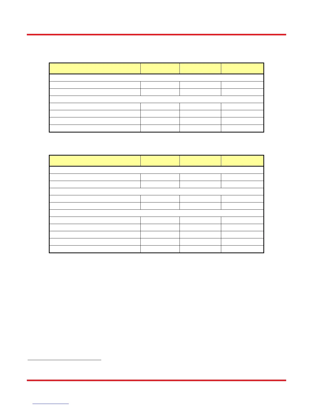
Performance
7.1.
Parameter Min Typical Max
Access Time (Adjacent Locations)
FW102C, FW102CNEB - <1 s -
FW212C, FW212CNEB - <0.5 s -
Access Time (Other Locations)
FW102C, FW102CNEB - 2.5 s -
FW212C, FW212CNEB - 2.5 s -
Accuracy / Repeatability
-
±2º
-
Expected Cycles
1.5 x 10
6
- -
Electrical
7.2.
Parameter Min Typical Max
BNC Input Trigger
Max Rate
- - 0.5 pulses/sec
Minimum Pulse Width
1.0 ms - -
BNC Input Trigger
1
Input High
3.3 V 4.5 V 5.3 V
Input Low
0.3 V 0.0 V 1.0 V
BNC Output Trigger
Output Pulse Width
9.0 ms 10.0 ms 11.0 ms
Output High
2
2.5 V (1 KΩ) 3.3 V (1.95 KΩ) 5.0 V (Hi Z)
Output Low
2
0.0 V 0.0 V 1.0 V
Power (DC Input, 1 A)
11.75 VDC 12 VDC 12.25 VDC
Operating Temperature
0 °C - 60 °C
1
The BNC input trigger is an active low input. The input has an internal 1 KΩ input resistor. Grounding the center conductor of the jack will
activate the trigger.
2
When operating as an output, the unit output driver is configured in series with a 1 KΩ resistor.
 Loading...