01/09/2014 Orion Optional Installation Manual
4
Fix the door-opener with 6 M6x40 screws, 6 M6 nuts and 6 washers.
At the same time, fix the casing roof covering over the holes that remain
outside the door-opener, with 2 M6x35-TS-PEI screws.
Figure 9 - Fixing the roof covering
Insert the slide [D] of the slidin
uide [C]. Fix the arm to
the automation, ensuring that it inserts into the housing of the arm
supports.
Insert the cover [E] and the two heads [F].
Figure 10 - Accessory assembly
1.3. Electrical connections
See the electrical diagram in the Installation Manual pertaining to each system. Please remember that the packaging
also includes the manufacturer's DITEC SPRINT installation manual.
Warning! The trimmers and DIPs affect the force limiting safety function. They must be set as instructed. If not,
the modifications will not be accepted and the IN LED will flash.
- Press the OPEN key for 4 seconds (IN LED flashes);
- Set the trimmers and select the DIPs within a 5 minute time limit;
- To complete the procedure, press the OPEN key for 2 seconds or wait for the time limit to expire.
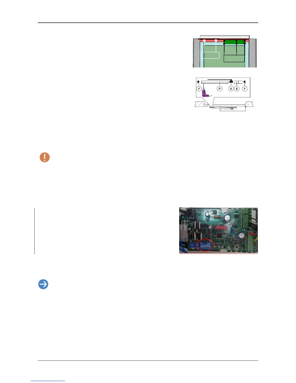
1.4. Setting the boards
Board on the actuato
Position the switches as shown below:
DIP1=OFF
DIP2=OFF
DIP3=OFF
DIP4=OFF (open to left)/ON (open to right)
DIP5=ON
DIP6=OFF
Bridge the safeties (G1-8, 1-9).
The TC trimmer located on the actuator is no used (and therefore should
not be adjusted).
Figure 11 - Actuator board
N.B.: each time it is turned on, the first opening or closing movement is carried out at low
speed and allows for the detection of stop levels (acquisition).
1.5. Final checks
Check that:
The switch on the actuator board is set to ON.
If the automation encounters an obstacle during closing, it detects this and re-opens.
If it encounters an obstacle during opening, it detects this and stops. In subsequent manoeuvres, the obstacle
is considered as a new stop until it is removed.
M6x40
 Loading...