01/09/2014 Orion Optional Installation Manual
6
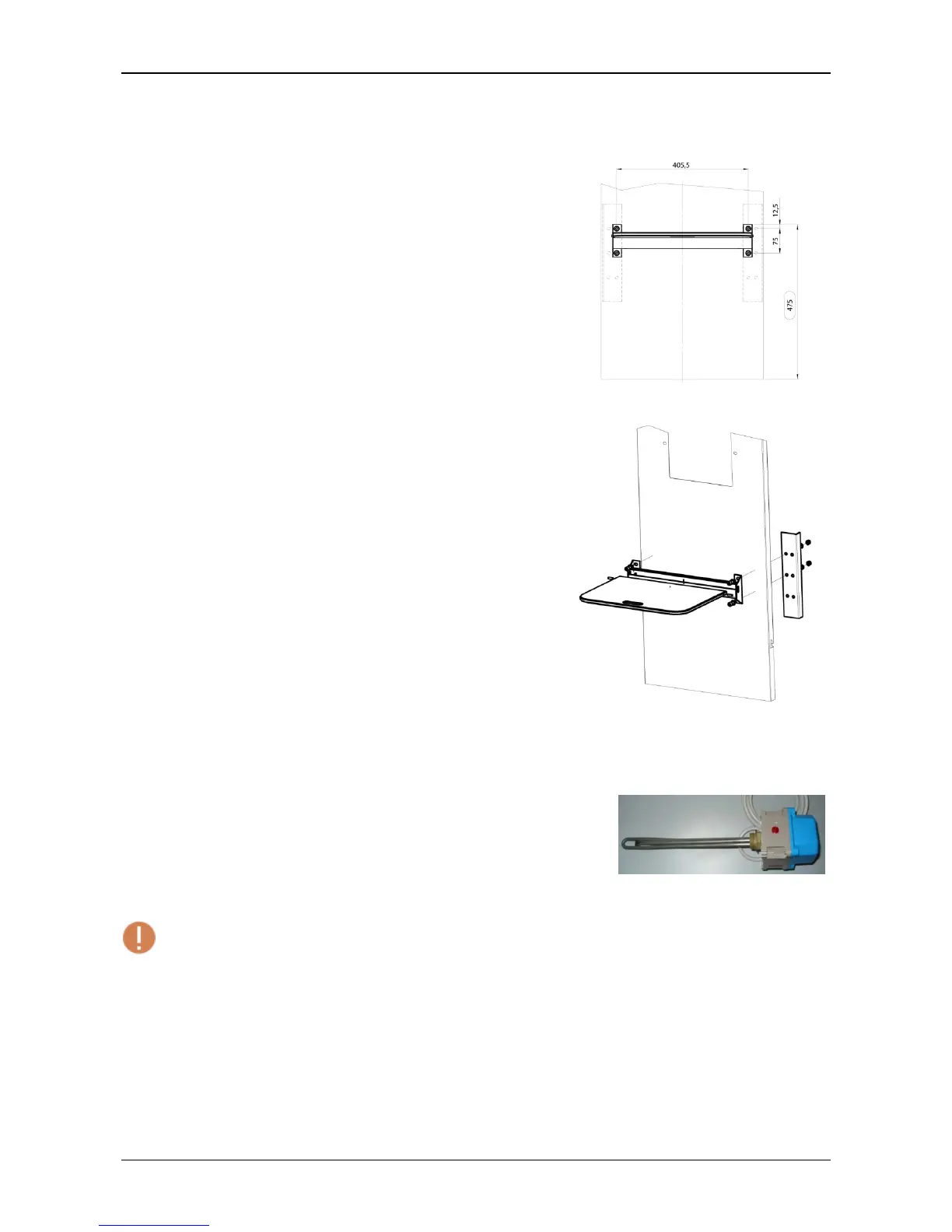
2. Seat
Position the seat in the position shown in fi
and create
two 8 mm diameter holes using the frame as a template.
Figure 13
Connect the seat support corners (see fi
Figure 14
3. Oil-heat resistance
The oil heat resistance is inserted within the tank of the oil hydraulic
control panel, by removing the 1" stopper to the side of the discharge
stopper. Insert Teflon on the thread of the resistance to guarantee a
better seal.
Figure 15 - Oil-heat resistance
Warning! Insertion must be carried out with the tank empty.
Open the resistance cover by actin
on the 4 cross-head screws to
adjust the thermostat in order to programme the intervention
temperature desired.
Connect the 3x1.5 resistance cable to the main clamps of the electrical
panel as shown in the diagram below.
Warning: power supply 220 V.
 Loading...