FUNCTION CHARACTERISTICS
34
NA011 - Manual - 05 - 2022
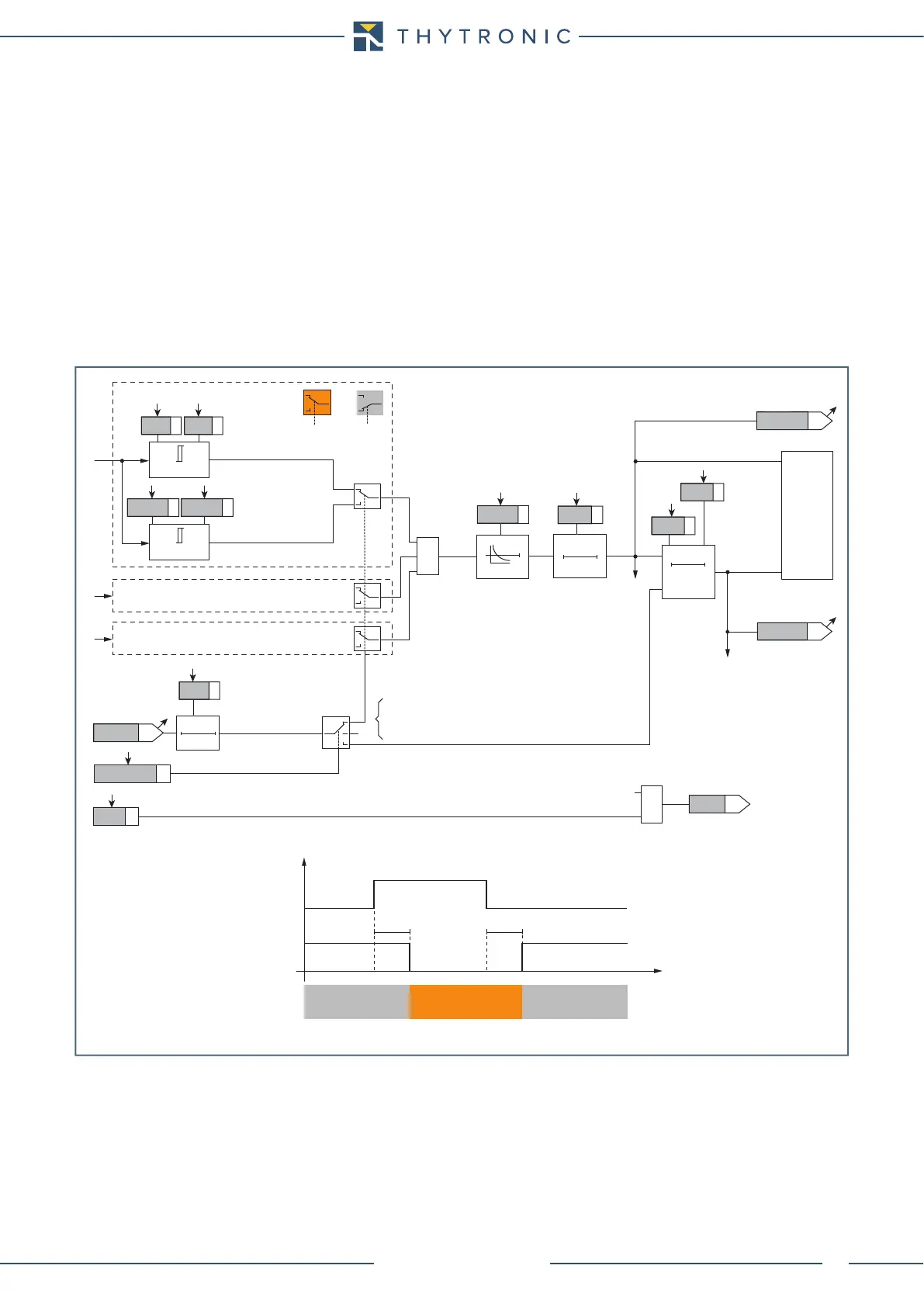
Each overcurrent element can produce the Breaker Failure output if the BF enable parameters are
set to Trip I>, Trip I>> and/or Trip I>>> inside the Set \ Breaker failure menu.
If the CLP function (Cold Load Pick-up) is enabled for element blocking, the selected threshold may
be blocked for an adjustable time interval tCLP>, tCLP>>, tCLP>>> parameters adjustable
inside the Set \ 50/51 \ I> Element (I>> Element) \ Setpoints menu), starting from the circuit breaker
closure.
This operating mode may be select by setting On-Blocking the ICLP>, ICLP>>, ICLP>>> pa-
rameters.
If the CLP function (Cold Load Pick-up) is enabled for threshold change, the selected threshold may
be changed for an adjustable time interval, starting from the circuit breaker closure.
This operating mode (ON-Changing = ICLP>, ICLP>>, ICLP>>>) and the concerning oper-
ating time within the CLP (tCLP>, tCLP>>, tCLP>>>) may be adjusted inside the Set \ 50/51
\ I> Element (I>> Element) \ Setpoints menus, whereas the operating thresholds within the CLP
(ICLP>def, ICLP>>def, ICLP>>>def) may be adjusted inside the Set \ 50/51 \ I> Element (I>>
Element, I>>> Element) \ Definite time (Inverse time) menus.
Fun_50-51S1.ai
I
L1
I
L2
t
>RES
T0
RESET
t
>
0T
≥ 1
t
>def
I
>def
I
>inv
t
>inv
t
>RES
Start I>
Trip I>
CB-State
(Pickup within CLP)
(Pickup outside CLP)
T 0
t
CLP>
ICLP>Mode
I
CLP
>def
t
CLP
>
I
CLP
>inv
I
L1
≥
I>
I
L1
≥
I>
BF Enable (ON≡ Enable)
I>BF
towards BF logic
I> BF
&
Trip I>
TRIPPING MATRIX
(LED+RELAYS)
I> Curve
0T
A
B
C
A =“1”A =“0 or OFF”
Output
t
CLP>
I
L3
t
CLP>
CB State CB OPEN CB CLOSED CB OPEN
Output t
CLP>
t
0.1 s
HIGH THRESHOLD/
BLOCK
LOW THRESHOLD/
UNBLOCK
HIGH THRESHOLD/
BLOCK
A = ON - Change setting
B = OFF
C = ON - Element blocking
I>TR-K
I>TR-L
I>ST-L
I>ST-K
Phase overcurrent (50/51) - First element logic diagram (I>)