112
FUNCTION CHARACTERISTICS
— Undercurrent - 37
Preface
One operation threshold, adjustable (I<
def
) with adjustable delay (t<
def
).
The threshold operates with definite time characteristic.
Operation and settings
Each of three side L currents are compared with the setting value (I<
def
). The start and trip logic may
be selected OR or AND.
With OR selection, a start is issued when at least one of the three currents goes down the adjustable
threshold (START); with AND selection, a start is issued when all the three currents go down the
adjustable threshold.
After expiry of the associated operate time (t<
def
), a trip command is issued; if instead the currents
exceed the threshold, the element is restored.
The element can be enabled or disabled by setting ON or OFF the State parameter inside the Set
\ Profile A (or B) \ Undecurrent-37 \ I< Element \ Definite time menu.
The undecurrent element may be disabled by means MMI. During the command, the trip output
relays I<TR-K (with latched or no-latched operation mode and, de-energized or energized logic) are
forced in the rest state, the“37 DISABLED” message is displayed and all the LEDs flash until the
command is ended.
The following block criteria is available:
Logical block (Block1)
If the I<BLK1 enabling parameter are set to ON and a binary input is designed for logical block
(Block1), the protection is blocked off whenever the given input is active.
The trip timer is held in reset condition, so the operate time counting starts when the input block
goes down.
[1]
The enabling parameter is available inside the Set \ Profile A (or B) \ Undercurrent - 37
\ I< Element \ Setpoints menu, while the Block1 function must be assigned to the selected binary
input inside the Set \ Board1(2) inputs \ Binary input IN1-1...INx-x menus.
The parameter may be adjusted independently for both profiles A or B.
Note 1 The description of the logical block (Block 1) function may be found in the “Logic Block” paragraph inside CONTROL AND MONITORING section.
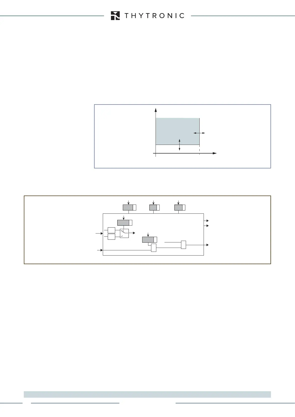
General operation time characteristic curve for the undercurrent element - 37
I<
def
t
I
t<
def
TRIP
General logic diagram of the undercurrent element
- 37
all-F37.ai
I
L1L
, I
L2L
, I
L3L
I< Element
Start I<
Trip I<
t
<
def
I<
def
State
Block1
BLK1I<
&
I<BLK1
Start I<
&
AND
OR
Logic37
XMR-D EQUIPMENT MANUAL
Ed. 2.9 - 02/2021
 Loading...
