FUNCTION CHARACTERISTICS
87
— Overflux - 24
Preface
The overfluxing protection is used as protection of the generator and connected transformer (eg au-
xiliary services transformer) against loss of insulation between the laminations of the magnetic circuit
leading to overheating produced by the iron losses due to the induction increase (over-excitation).
The overfluxing condition may occur:
• With generators disconnected from the network during start-up or standing, due to automatic con-
trol of the voltage regulator which, at low frequency, forces excitation increasing the flux in order
to keep the voltage constant.
• For failure of the voltage regulator in automatic control or wrong operations on manual control.
• Following the over-voltage produced by the shedding of a significant load, whilst the voltage regu-
lator is not operating sufficiently quickly to reduce the overvoltage.
The device measures the relationship U/f, which is proportion to the magnetic flux, the calculation
is based on the ratio between the maximum voltage of the three phase-to-phase voltages and the
frequency.
To better adapt itself to the limit curve of the admissible induction of the generator and transformer,
the protective device makes use of an alarm (U/f)
AL
and two, independently adjustable and delayed
(t
U/fAL
, t
U/f
>, t
U/f
>>), trip thresholds (U/f)> and (U/f)>>.
A start is issued when the U/f=U
MAX
/f ratio goes up the adjustable threshold; after expiry of the as-
sociated operate time a trip command is issued; if instead the ratio drops below the threshold, the
element is restored.
The alarm threshold (U/f)
AL
have a definite time characteristic.
The first trip threshold (U/f)> may be programmed with definite or inverse time characteristic by set-
ting the
U/f>Timecharacteristic parameter (DEFINITE,IECtypeA,IECtypeB,IECtypeC)
available inside the Set \ Profile A (or B) \ Overexcitation - 24 \ (U/f)> Element \ Setpoints menu.
The second threshold (U/f)>> have a definite time characteristic.
The operate time, corresponding to a U/f ratio of 1.5 times the threshold, can be determined
analytically using the formulas below:
where:
t: operate time
U/f: input value
(U/f )>: threshold setting
t
U/f
>:
operate time setting
Minimum ratio(U/f ) : 1.1 (U/f)>
Minimum operate time: 0.1 s
Range where the equation is valid: 1.1 ≤ (U/f )> ≤ 5, the upper limit for measuring is 10 U
n
/f
n
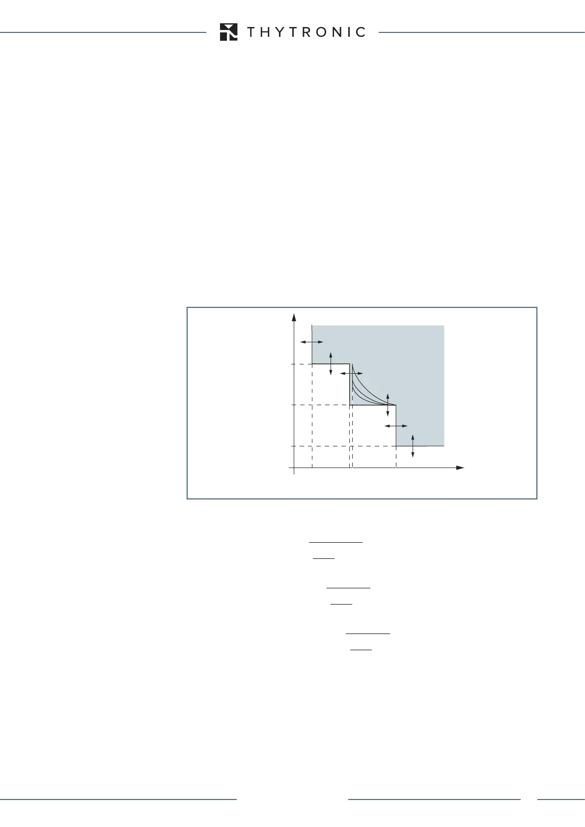
t-int-F24.ai
(U/f)
AL
U/f(U/f)>
t
U/f
>
t
U/fAL
t
t
U/f
>>
(U/f)>>
1.1(U/f)>
General operation time characteristic for the overflux elements - 24
TRIP
DEP A: type A IEC inverse time t
U/f
0.02
/
1
/
U f
U f
=
−
>
DEP B: type B IEC very inverse time
t
DEP C: type C IEC extremely inverse time
t
U/f
>
0.5
/
1
/
t
U f
U f
⋅
=
−
>
U/f
>
2
1.25
/
/
t
U f
U f
⋅
=
−
>
XMR-D EQUIPMENT MANUAL
Ed. 2.9 - 02/2021
 Loading...
