168
FUNCTION CHARACTERISTICS
— Inadvertent energization - 50/27
Preface
Connection of a standing (or non-yet synchronized) generator to the network following fast actuation
of the circuit breaker is the cause of severe damage to the machinery; under such conditions, it op-
erates as an asynchronous machine with high flow values, hence with high currents induced in the
rotor, causing very rapid overheating.
The protective element consists of a Overcurrent enabled by the condition of the standing machine
after an adjustable time.
Operation and settings
The following measures are involved:
• U
L1
, U
L2
, U
L3
fundamental component of phase-to-neutral voltages,
• I
L1
, I
L2
, I
L3
fundamental component of line currents.
The logic relating to the standing machinery depends on the positioning of the VT used to measure
the voltages, whether on the generator side, or network side with respect to the mains breaker.
• With “GENERATOR SIDE VT” set-up, the condition of the standing machine is detected when all
three phase voltages U
L1
, U
L2
, U
L3
are less than the adjustable threshold U
UE
<, in the absence of
tripping of the VT monitoring function (74VT) and when the machine breaker is open. The tripping
occurs if the element is enabled and at least one of the three phase currents exceeds the adjust-
able threshold I
UE
>. The restoration of enabling for trip comes after an adjustable time t
UE-RES
.
• With “NETWORK SIDE VT” set-up, the condition of the standing machine is detected when all three
phase voltages U
L1
, U
L2
, U
L3
are less than the adjustable threshold U
UE
<, and with no tripping of the
VT monitoring function (74VT) and when the machine breaker is open. The tripping occurs if the
element is enabled and at least one of the three phase currents I
L1
, I
L2
, I
L3
exceeds the adjustable
threshold I
UE
>. The restoration of enabling for trip comes after an adjustable time t
UE-RES
.
The element can be enabled or disabled by setting ON or OFF the
50/27 element parameter
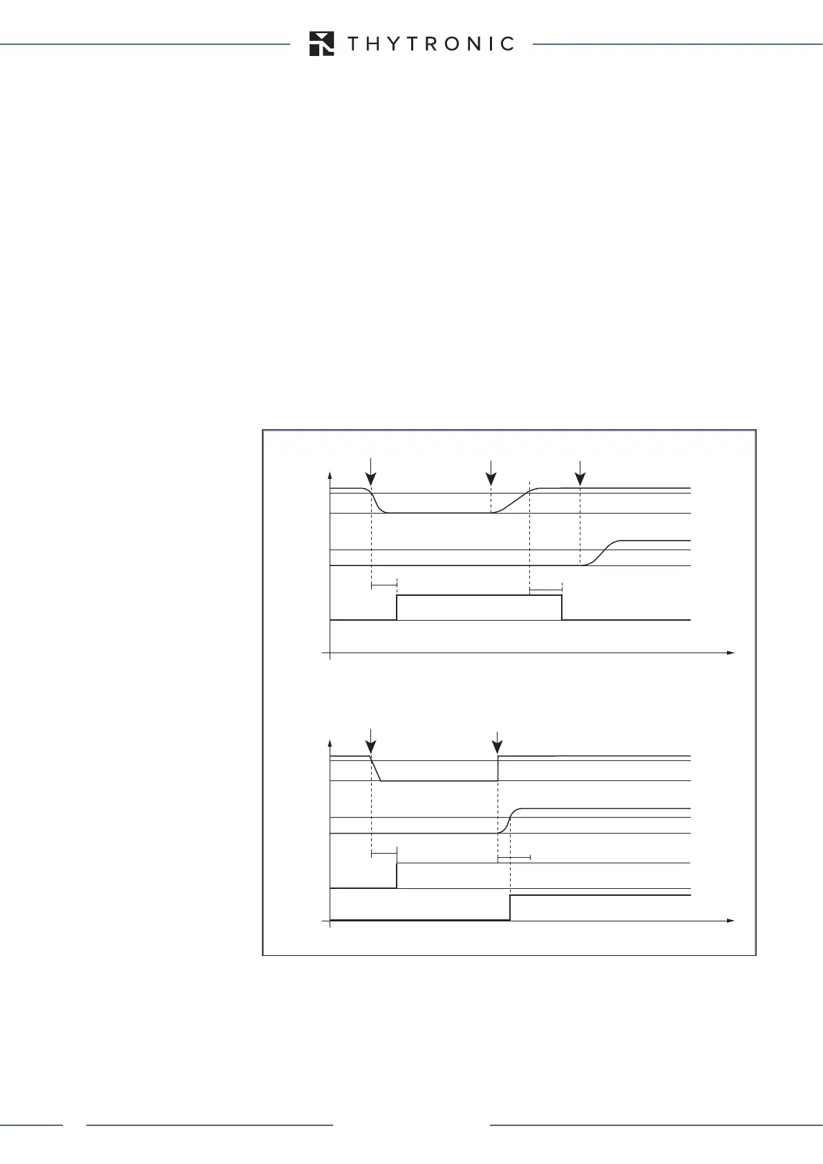
A) Right CB closing
Start 50+27
Stop
Stop
Trip 50+27
U
UE<
I
UE>
t
UE
t
t
UE-RES
Start sync.
Right CB closing
B) CB inadvertent closing
Start 50+27
Trip 50+27
Max I
L1
...I
L3
U
UE<
I
UE>
Max U
L1
...U
L3
Max I
L1
...I
L3
Max U
L1
...U
L3
t
UE
t
t
UE-RES
CB inadvertent closing
Inadvertent energization (50N+27) - Timers
XMR-D EQUIPMENT MANUAL
Ed. 2.9 - 02/2021
 Loading...
