334
FUNCTION CHARACTERISTICS
4.5 CONTROL AND MONITORING
— Synchrocheck - 25
Preface
The protection is available in the XMR-V, XMR-P and XMR-G versions.
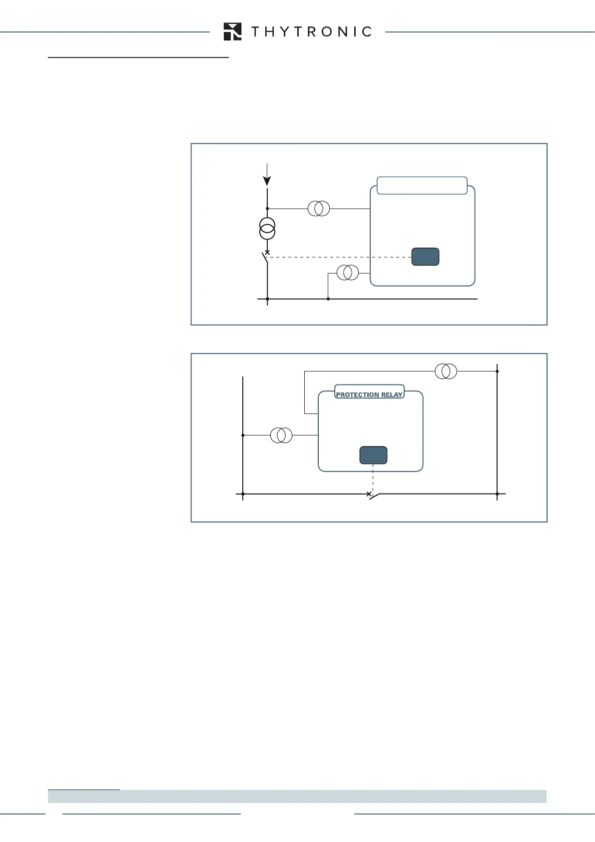
The synchrocheck function verifies that the connection between two sections of a power system
can take place without endangering the stability of the power system. Typical applications are:
• the synchronization of an incoming power supply and a bus-bar, eg. the connection of a line powe-
red by a generator (cogeneration) and bus-bars fed by the Distributor:
• synchro check of two busbars via bus coupler.
Inputs
The two grid measured voltages are employed:
• V
1
: reference input (three-phases or one-phase); by means of the Synchrocheckvoltageme-
asureV1 parameter (phase-to-phase voltage U
12
or phase-to-neutral voltage U
L1
, available inside
the Set \ Base menu the voltage input can be selected.
1
• V
2
: one phase input voltage to be synchronized. Input is used normally used for measuring the re-
sidual voltage (B9-B10 terminals); by means of the
VoltagemeasureUEorV2 parameter (U
E
or
V
2
), available inside the Set \ Base menu, the voltage input can be selected.
[1]
Being the native input unavailable, the residual voltage can be calculated by vector sum from the
three phase voltages.
If a power transformer between the two voltage measurement inputs exists (eg Fig.1), a sw adapta-
tion which allows to compensate the connection group is available without the need of interposing
external adapters; the phase compensation can be carried out by means of the parameter
V1-V2
Phasecorrection, available inside the Set \ Base menu.
[1]
Output relays
The synchrocheck function can activate one or more relays according to the usual allocation matrix
criterion .
The pulse operating mode must be select (Set \ Board 1 outputs menu) and the pulse width must be
set according to the circuit breaker requirements.
Operating mode
The following three operating modes can be select:
• 0 - Synchro check between two live sections of the plant (synchronous or asynchronous),
• 1 - Synchro check between live busbars and dead line,
• 2 - Synchro check between live line and dead busbars.
Note 1 To change the parameter, you must operate at Level 1
BUSBAR
SYNC command
FEEDER
Fig. 1 - Infeed synchronisation
V
2
(one-phase input)
V
1
(three-phase input)
25
PROTECTION RELAY
XMR
BUSBAR 1
BUSBAR 2
Fig.2 - Busbar synchronization
25
Close command
XMR
V
2
V
1
XMR-D EQUIPMENT MANUAL
Ed. 2.9 - 02/2021
 Loading...
