128
FUNCTION CHARACTERISTICS
Use of binary inputs:
• If the I2>BLK2IN and/or I2>>BLK2IN parameters are set to ON and a binary input is desi-
gned for selective block (Block2), the protection is blocked off by phase elements (Block2 Iph)
or by any protection element (Block2 Iph/IE) according the selectivity block criteria.
4
The enable
I2>BLK2IN and/or I2>>BLK2IN parameters are available inside the Set \ Profile A (or B) \
Negative sequence overcurrent - 46LT \ I2> Element (I2>> Element) \ Setpoints menus, while the
Block2 Iph and
Block2Iph/IE functions must be assigned to the selected binary inputs inside
the Set \ Board 1(2) inputs \ Binary input IN1-1...(IN1-x) menus.
Use of committed pilot wire output BLOUT1:
• The information about phase or phase+earth block may be select programming the ModeBLOUT1
parameter (
OFF-ONIPh-ONIPh/IE-ONIE) inside Set \ Profile A (or B) \ Selective block-
BLOCK2 \ Selective block OUT menus.
Use of output relay:
• If the I2>BLK2OUTand/orI2>>BLK2OUT enable parameters are set to ON and a output relay
is designed for selective block (Block2), the protection issues a block output by phase elements
(BLK2OUT-Iph) or by any protection element (BLK2OUT-Iph/IE), whenever the given element (Start
I>, Start I>> e/o Start I>>>) becomes active. The enable
I2>BLK2OUTand/orI2>>BLK2OUT
parameters (ON or OFF) are available inside the Set \ Profile A (or B) \ Negative sequence over-
current - 46LT \ I2> Element (I2>> Element) \ Setpoints menus, while the
BLK2OUT-Iph-K,
BLK2OUT-Iph/IE-K and/or BLK2OUT-IE-K output relays and LEDs (BLK2OUT-Iph-L,
BLK2OUT-Iph/IE-Le/o BLK2OUT-IE-L) must be select inside the Set \ Profile A (or B) \ Selecti-
ve block-BLOCK2 \ Selective block OUT menu.
All parameters can be set separately for A and B setting profiles.
all-F46.ai
I
L1
I
L2
I
L3
I
L1
I
L2
I
L3
BLK1I2>>
I2>> Element
BLK2OUT
Start I2>>
Start I2>>
Trip I2>>
&
I2> disbyI>>
&
I2>>BLK1
&
I2>>BLK2IN
t2
>>
def
I2CLP>>
def
I2>>
def
t2CLP>>
t2
>>
RES
I2>> Enable
I2> inhibition
Block1
BLK1I2>
CLPI2>
CLPI2>>
I2> Element
BLK2OUT
BLK2INI2>
BLK2INI>>
Start I2>
Trip I2>
&
I2>BLK1
Block2
&
I2>BLK2IN
I2>BLK2OUT
Start I2>
&
I2>>BLK2OUT
Start I2>>
&
Block1
Block2
t2>
def
I2CLP>
def
I2>
def
t2>
inv
I2CLP>
inv
I2>
inv
I2>Curve
t2CLP>
t2>
RES
I2> Enable
Start I2>
&
Start I2>>
&
Start I2>>
&
Start I2>
&
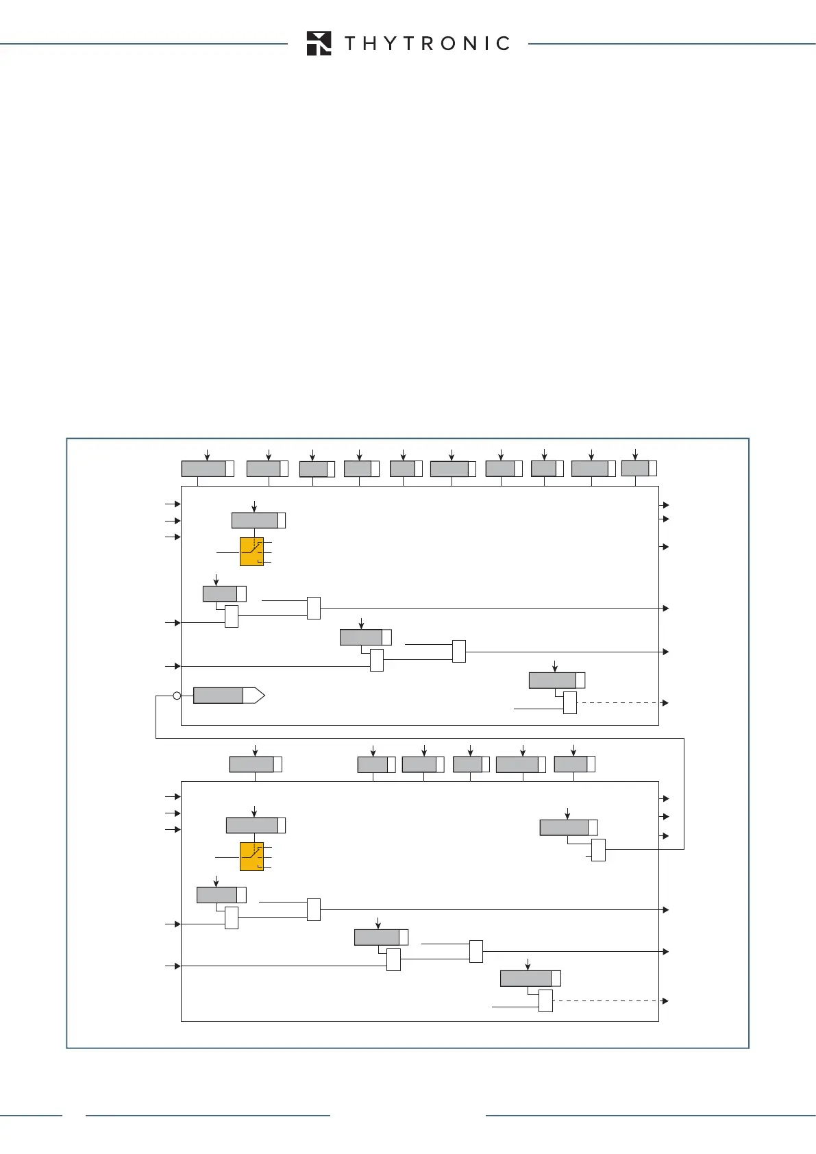
General logic diagram of the negative sequence overcurrent elements - 46LT
I2CLP>Mode
Change setting
Element blocking
OFF
I2CLP>>Mode
Change setting
Element blocking
OFF
XMR-D EQUIPMENT MANUAL
Ed. 2.9 - 02/2021
 Loading...
