FUNCTION CHARACTERISTICS
121
Operation and settings
The resistive R
L1
and reactive X
L1
components and the cosf
ZL1
power factor, concerning the Z
L1
impedance (phase voltage U
L1
phase current I
L1
ratio) are calculated:
Z
L1
= U
L1
/I
L1
R
L1
= Z
L1
cosf
ZL1
X
L1
= Z
L1
sinf
ZL1
where Z
L1
and f
ZL1
are the impedance module and displacement Z
L1
, U
L1
is the L1 phase-to neutral
voltage, I
L1
is the L1 phase current phasor.
Convention: f
ZL1
positive with current I
L1
lagging the voltage U
L1
.
Setting for GENERATOR mode
Reference: connection diagram shown in fig. 1 and 2.
The start of the alarm element is issued when both the following conditions are filled:
• X
L1
≤ KR
L1
• R
L1
≤ 0
or when both the following conditions are filled:
• X
L1
≤ -KR
L1
• R
L1
> 0
where K is the adjustable angular coefficient (10° ≤ a ≤ 75°, K = tana).
After expiry of the associated operate time (t
40AL
) a trip command is issued.
The start of the first element is issued when both the conditions concerning the alarm element are
filled and the R
L1
and X
L1
computed values are placed inside the circle with equation:
R
L1
2
+(X
L1
+ X
C1
)
2
≤ (X
D1
/2)
2
1)
where the absolute coordinate of the center is X
C1
and the diameter X
D1
are adjustable.
After expiry of the associated operate time (t
XC1XD1
) a trip command is issued.
X
L1
(p.u. Z
nf
)
αα
R
L1
(p.u. Z
nf
)
TRIP
TRIP
ALARM
X
D2
X
C1
X
D1
NO TRIP
NO TRIP
NO TRIP
X
C2
General operation R-X characteristic for the loss of field element - 40 in the RL1-XL1 plane with
Mode40 = GENERATOR setting
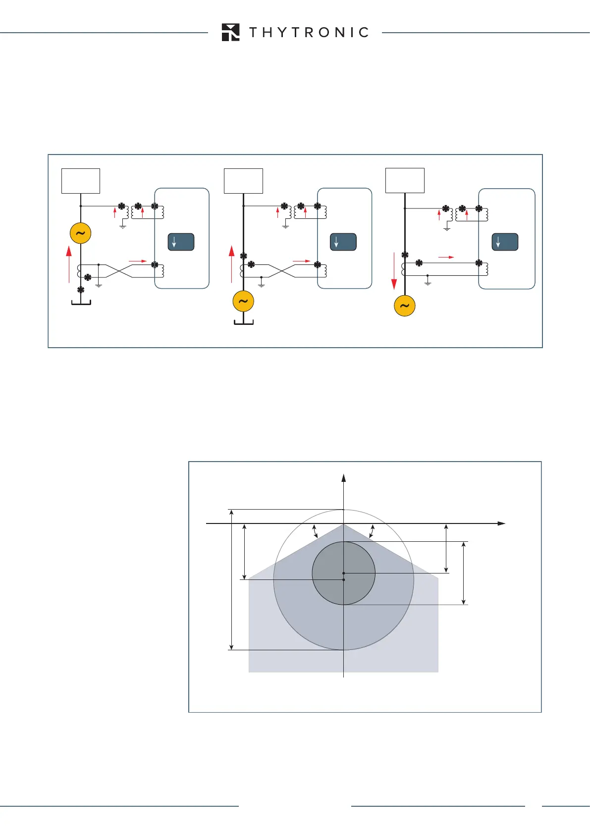
Loss of field (40) protection for a synchronous machine normally working as generator (fig.1 and 2) or motor (fig. 3)
Fig. 1 Fig. 2 Fig. 3
SYSTEM
U
L1
U
L2
U
L3
VOLTAGE
INPUTS
CURRENT
INPUTS
SYSTEM
U
L1
U
L2
U
L3
I
L1L
I
L2L
I
L3L
I
L1L
I
L2L
I
L3L
I
L1L
I
L2L
I
L3L
VOLTAGE
INPUTS
CURRENT
INPUTS
XMR-x XMR-x XMR-x
VOLTAGE
INPUTS
CURRENT
INPUTS
SYSTEM
U
L1
U
L2
U
L3
40 40 40
CTs star side CTs line side
XMR-D EQUIPMENT MANUAL
Ed. 2.9 - 02/2021
 Loading...
