FUNCTION CHARACTERISTICS
149
Fun_49_AL1.ai
Common configuration
&
dDθ/dt + Dθ/T = (Ith/I
B
)
2
/T
Init DTheta
Dθ
≥
DthAL1
DthAL1
Binary input INx
T 0
Logic
INx
t
ON
INx
t
ON
INx
t
OFF
T0
n.o.
n.c.
INx
t
OFF
I
th
≥1
K
INR
DthAL1
CB-State
Start I
2ndh>
ON≡Enable element
(Pickup within CLP)
(Pickup outside CLP)
Pickup - CLP setting change
Block1, Block2, Block4
T 0
t
DthCLP
&
2nd harmonic restraint enable (ON≡Enable)
Dth2ndh-REST
DthCLPMode
t
DthCLP
I
th
∙
K
INR
TRIPPING MATRIX
(LED+RELAYS)
A
B
C
A =“1”A =“0 or OFF”
Output
t
DthCLP
DthAL1 Enable
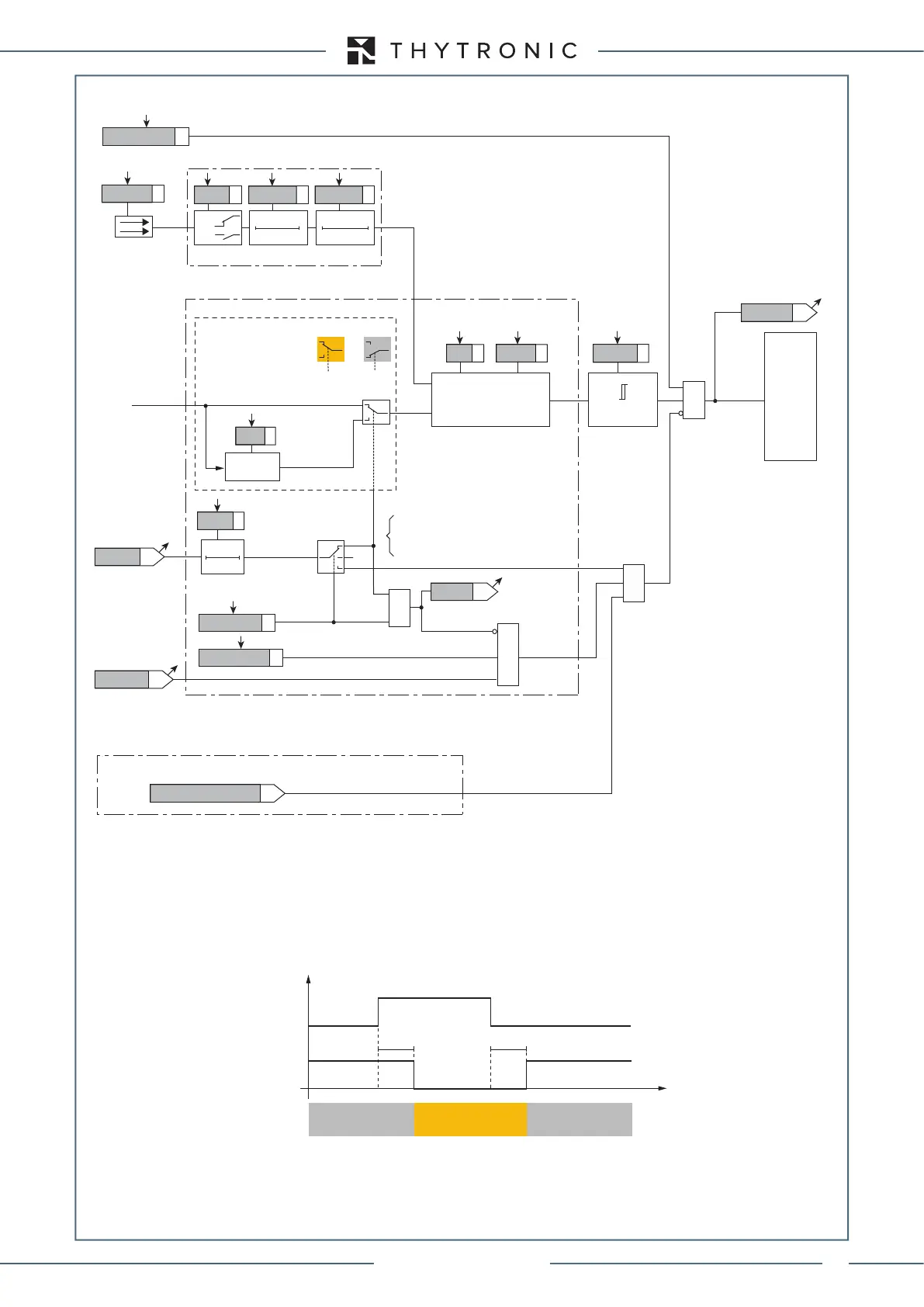
DThhAL1 thermal image (49) block diagram
t
DthCLP
CB State CB OPEN CB CLOSED CB OPEN
Output t
DthCLP
t
0.1 s
HIGH THRESHOLD/
BLOCK
LOW THRESHOLD/
UNBLOCK
HIGH THRESHOLD/
BLOCK
A = ON - Change setting
B = OFF
C = ON - Element blocking
DthAL1-L
DthAL1-K
≥1
CLP Dth
T DthIN
Thermal image (49LT) - Logic diagram of the first alarm threshold
XMR-D EQUIPMENT MANUAL
Ed. 2.9 - 02/2021
 Loading...
