FUNCTION CHARACTERISTICS
235
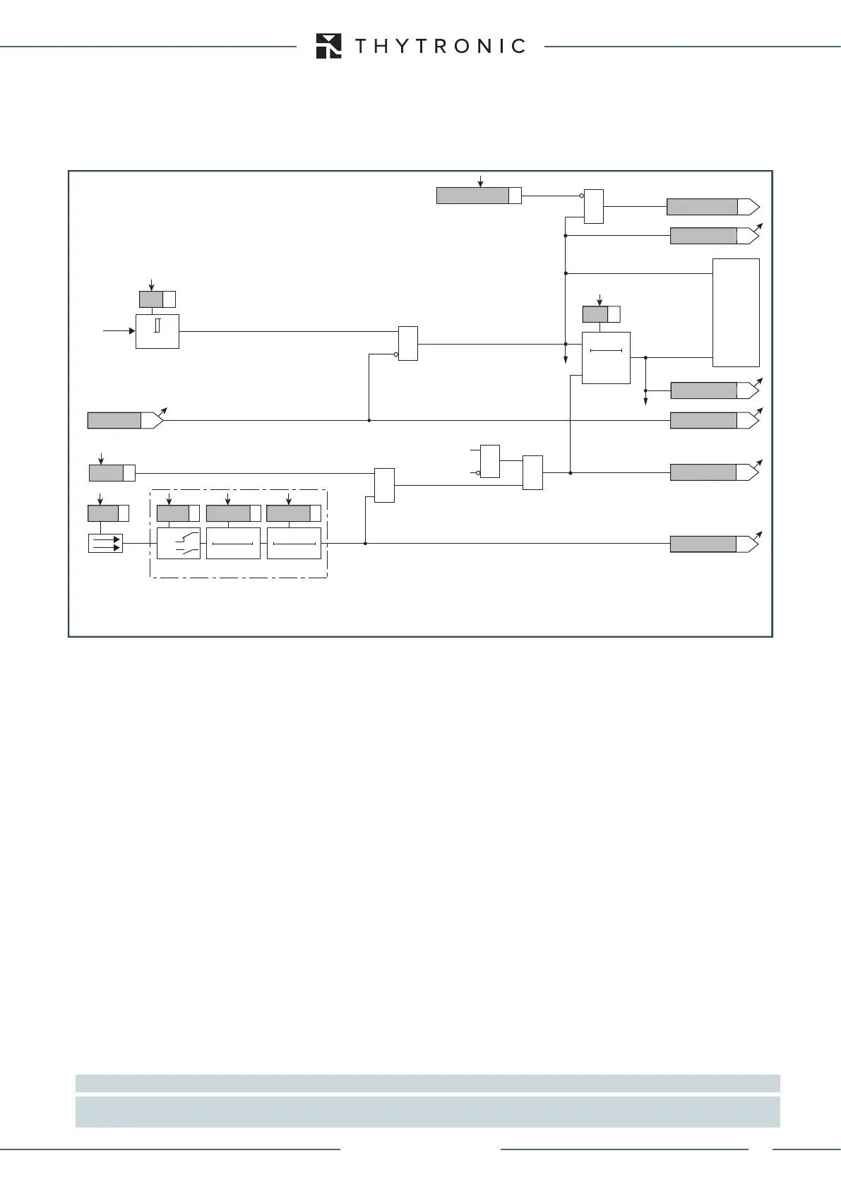
Breaker failure (BF)
Each thresholds (RFAL<, RF<<) can be associated to BF (H) and BF (L) protection by activating the
relative parameter in the matrices “Selection of function tripping for BF (H)” or “Selection of function
tripping for BF (L)” in relevant BF menus
[1]
:
• Set \ Profile A (or B) \ Breaker failure - BF side H
• Set \ Profile A (or B) \ Breaker failure - BF side L
Logical block (Block1)
If the Block1 enabling parameters are set to ON and a binary input is designed for logical block
(Block1), the protection is blocked off whenever the given input is active.
The trip timer is held in reset condition, so the operate time counting starts when the input block goes
down.
[2]
The enabling parameters are available inside the Profile A (or B) \ Rotor earth fault - 64F
\ Alarm configuration, (Trip configuration) \ Setpoints menus, while the Block1 function must be
assigned to the selected binary input inside the Common parameters \ Binary input allocation menu.
menus (IN1 or INx matching).
Block3
The protection is enabled inside the range 20...70 Hz (Block3).
Note 1 The common settings concerning the Breaker failure protection are adjustable inside the Breaker Failure - BF menu.
Note 2 The exhaustive treatment of the logical block (Block 1) function may be found in the “Logic Block” paragraph inside CONTROL AND MONITO-
RING section.
Fun-F64F_S2.ai
IF Start
=0 if 20≤f≤75 Hz
&
RESET
t
RF<<
0T
TRIPPING MATRIX
(LED+RELAYS)
t
RF<<
R
F
<< Start
R
F
<< Start
R
F
<< Start
R
F
<< Trip
R
F
<< Trip
R
F
<< Trip
F64FS2 Block3
R
F
<< Block1
&
&
&
Enable (ON≡Enable)
Block1 input (ON≡Block)
Block1
Block1
Block1
R
F
≤
R
F
<
R
F
<<
&
(ON≡
Inhibit
)
R
FAL
< Inhibition
R
FAL
< Inhibition
R
F
Binary input INx (x=1...8-16)
T 0
Logic
INx
t
ON
INx
t
ON
INx
t
OFF
T0
n.o.
n.c.
INx
t
OFF
Logic diagram concerning the second threshold (RF<<) of the rotor earth fault element - 64F
XMR-D EQUIPMENT MANUAL
Ed. 2.9 - 02/2021
 Loading...
