FUNCTION CHARACTERISTICS
247
Projection
If the projection principle and the one of three - 1/3 operation logic are selected, the start of any 67
threshold becomes active when the following condition are contemporaneously active:
• If the operation mode is not switched to “not directional” (by the 74VT function), when the
projection of the current phasor on the characteristic axis I
Lx
cos(ThetaP>-a
x
), I
Lx
cos(ThetaP>>-a
x
),
I
Lx
cos(ThetaP>>>-a
x
), I
Lx
cos(ThetaP>>>>-a
x
) where x=1, 2, 3 of at least one phase is positive and
overcomes the setting threshold (I
PD>
, I
PD>>
,
I
PD>>>
, I
PD>>>>
), a start signal is issued.
• If the operation mode is switched to “not directional” (by the 74VT function), when at least one
phase current (I
L1
, I
L2
, I
L3
) overcomes the setting threshold (I
PD>
, I
PD>>
,
I
PD>>>
, I
PD>>>>
), a start signal is
issued. (no displacement or projection condition are required for tripping).
After expiry of the associated operate time (t
PD>
, t
PD>>
,
t
PD>>>
, t
PD>>>>
) a trip command is issued; if inste-
ad the above conditions don’t remain valid, the element it is restored.
If the projection principle and the two of three - 2/3 operation logic are selected, the start of any 67
threshold becomes active when the following condition are contemporaneously active:
• If the operation mode is not switched to “not directional” (by the 74VT function), when the
projection of the current phasor on the characteristic axis I
Lx
cos(ThetaP>-a
x
), I
Lx
cos(ThetaP>>-a
x
),
I
Lx
cos(ThetaP>>>-a
x
), I
Lx
cos(ThetaP>>-a
x
where x=1 e 2, 2 e 3, 3 e 1) of at least two phases is posi-
tive and overcomes the setting threshold (I
PD>
, I
PD>>
,
I
PD>>>
, I
PD>>>>
), a start signal is issued
• If the operation mode is switched to “not directional” (by the 74VT function), when at least a pair of
phase currents (I
L1
e I
L2
, I
L2
e I
L3
, I
L3
e I
L1
) overcomes the setting threshold (I
PD>
, I
PD>>
,
I
PD>>>
, I
PD>>>>
), a
start signal is issued. (no displacement or projection condition are required for tripping).
After expiry of the associated operate time (t
PD>
, t
PD>>
,
t
PD>>>
, t
PD>>>>
) a trip command is issued; if inste-
ad the above conditions don’t remain valid, the element it is restored.
All directional overcurrent elements can be enabled or disabled by setting ON or OFF the IPD>
Enable,
IPD>>Enable,, IPD>>>Enablee/o IPD>>>>Enableparameters inside the Set \
Profile A (or B) \ Directional phase overcurrent-67 \ IPD> Element (IPD>> Element, IPD>>> Element,
IPD>>> Element) \ Setpoints menus.
The first and second overcurrent element can be programmed with definite or inverse time cha-
racteristic by setting the
IPD>Curveand/orIPD>>Curve (INDIPENDENTE,IEC/BSA,IEC/
BS B, IEC/BS C, ANSI/IEE MI, ANSI/IEE VI, ANSI/IEE EI, RECTIFIER, I2t, EM) avai-
lable inside the Set \ Profile A (or B) \ Directional phase overcurrent-67 \ IPD> Element (IPD>> Ele-
ment) \ Setpoints menus.
The trip of IPD> element may be inhibited by the start of the second, third and/or fourth ele-
ment (I
PD>>
,
I
PD>>>
, I
PD>>>>
) by setting ON the Disable IPD> by start IPD>>, Disable IPD> by start
IPD>>>, Disable IPD> by start IPD>>>> (
IPD>disbyIPD>>, IPD>disbyIPD>>>, IPD>di-
sbyI>>>>) parameters available inside the Set \ Profile A (or B) \ Directional phase overcur-
rent-67\ IPD>> Element (IPD>>> Element, IPD>>>> Element) \ Setpoints menus.
Similarly the trip of the:
• IPD>> element may be inhibited by start of the third and/or fourth element (IPD>>> and/or IPD>>>>)
by setting ON the Disable IPD>> by start IPD>>>, start IPD>>>> (
IPD>>disbyIPD>>>,
IPD>>disbyIPD>>>>) parameter available inside the Set \ Profile A (or B) \ Directional phase
overcurrent-67 \ IPD>>> Element (IPD>>>> Element) \ Setpoints menus.
• IPD>>> element may be inhibited by start of the fourth element (IPD>>>>) by setting ON the Di-
sable IPD>>> by start IPD>>>> (IPD>>>disbyIPD>>>>) parameter available inside the Set \
Profile A (or B) \ Directional phase overcurrent-67 \ IPD>>>> Element \ Setpoints menu.
All the named parameters can be set separately for Profile A and Profile B.
An adjustable reset time delay is provided for every threshold (t
PD>RES
, t
PD>>RES
, t
PD>>>RES
, t
PD>>>>RES
)
Breaker failure (BF)
Each thresholds (IPD>, IPD>>, IPD>>>, IPD>>>>) can be associated to BF (H) and BF (L) protection
by activating the relative parameter in the matrices “Selection of function tripping for BF (H)” or
“Selection of function tripping for BF (L)” in relevant BF menus
2
:
• Set \ Profile A (or B) \ Breaker failure - BF side H
• Set \ Profile A (or B) \ Breaker failure - BF side L
Note 2 The common settings concerning the Breaker failure protection are adjustable inside the Breaker Failure - BF menu.
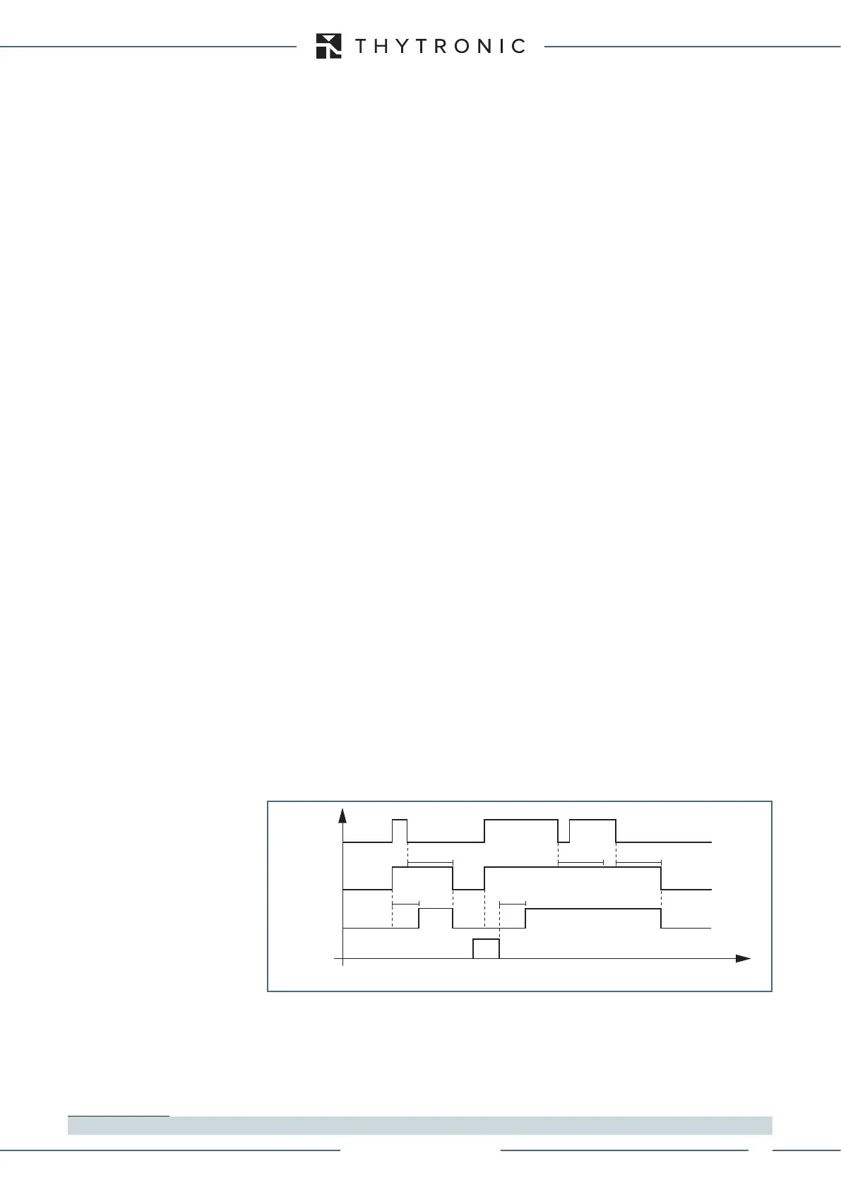
IPD> Start
IPD> Trip
t
PD>
t
PD>
RESET
INPUT
t
PD>RES
t
PD>RES
t
PD>RES
t
IPD> element timers - 67
XMR-D EQUIPMENT MANUAL
Ed. 2.9 - 02/2021
 Loading...
