FUNCTION CHARACTERISTICS
261
VT supervision
For all the four thresholds (I
ED>
, I
ED>>
,
I
ED>>>
, I
ED>>>>
), the operating mode when the 74VT function is
active may be defined:
• OFF: no action are issued by 74VT.
• Block: all the four thresholds are blocked when the 74VT function is active.
• Not directional: all the four thresholds are switched from directional to not directional criteria
when the 74VT function is active.
The 74VT information may issued from internal 74VT function or from an external signal acquired by
means a binary input.
If a binary input is designed for 74VText, for all the four thresholds, the operating mode when the 74VT
function is active may be defined:
• OFF: no action are issued by 74VT.
• Block: all the four thresholds are blocked when the 74VT external signal is active.
• Not directional: all the four thresholds are switched from directional to not directional criteria
when the 74VT external signal is active.
Malfunctioning of the directional overcurrent elements can be avoided when VTs secondary fault
will arise (fuse or MCB tripping) by switching the overcurrent directional to non directional overcur-
rent protection
The 74VTint67N and
74VText67Nparameters may be set as OFF,Block,Notdirectionalinside
the Set \ Profile A (or B) \ Directional earth fault overcurrent-67N \ Common configuration menu,
while the 74VText function must be assigned to the selected binary inputs inside the Set \ Board
1(2) inputs \ Binary input IN1-1...(IN1-x) menus.
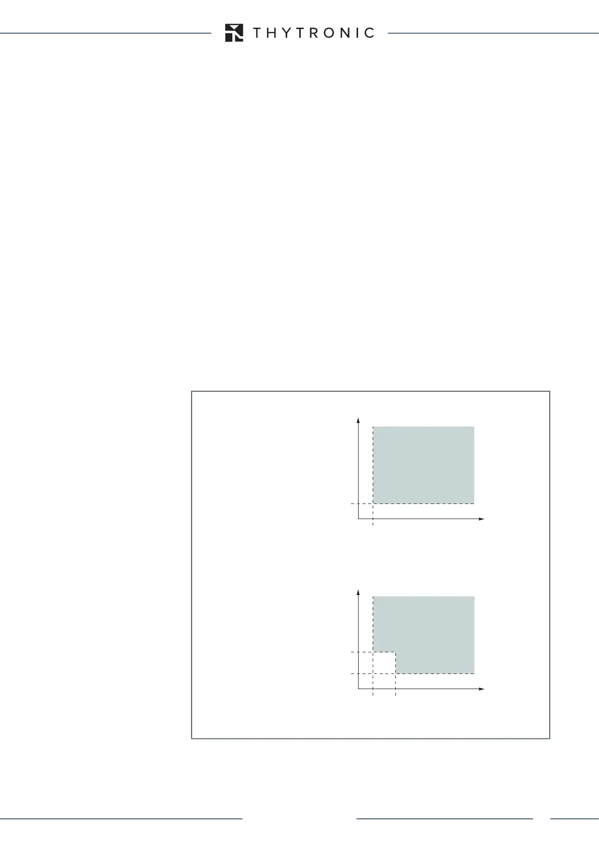
For all the four thresholds (common for all thresholds) an insensibility zone may be enabled in the
voltage-current plane.
If enabled, the insensibility zone is user adjustable by means the M multiplier (common for all thre-
sholds); the rectangle defined by the current and voltage thresholds and the same multiplied by M
becomes a No trip zone.
Such insensibility zone may be useful to avoid unwanted trip in the presence of some fixed residual
current and/or voltage (e.g. CT and or VT errors in the residual measurements).
The Insens-Zone (OFF, ON) and M parameters may be adjusted inside the Set \ Profile A (or B) \
Directional earth fault overcurrent-67N \ Common configuration menu.
Module
If the module principle and the operation mode is not switched to “not directional” (by the 74VT
function), the start of any 67N threshold becomes active when the following A) and B) conditions
are contemporaneously active:
A) in the “Insens-Zone=OFF” operating mode:
- The residual current (I
E2
) fundamental component overcomes the threshold (I
ED>
, I
ED>>
,
I
ED>>>
,
char-F67N-IeUe.ai
Voltage/current characteristic concerning the earth fault overcurrent element - 67N
with insensibility zone disabled
Voltage/current characteristic concerning the ground directional overcurrent - 67N
with insensibility zone enabled
I
E2
I
ED
>, I
ED
>>, I
ED
>>>, I
ED
>>>>
M∙I
ED
>, M∙I
ED
>>, M∙I
ED
>>>, M∙I
ED
>>>>
M∙U
ED
>, M∙U
ED
>>, M∙U
ED
>>>, M∙U
ED
>>>>
TRIP
U
E
U
EC
I
E2
I
ED
>, I
ED
>>, I
ED
>>>, I
ED
>>>>
U
ED
>, U
ED
>>, U
ED
>>>, U
ED
>>>>
U
ED
>, U
ED
>>, U
ED
>>>, U
ED
>>>>
TRIP
U
E
U
EC
XMR-D EQUIPMENT MANUAL
Ed. 2.9 - 02/2021
 Loading...
