Version C January 2021
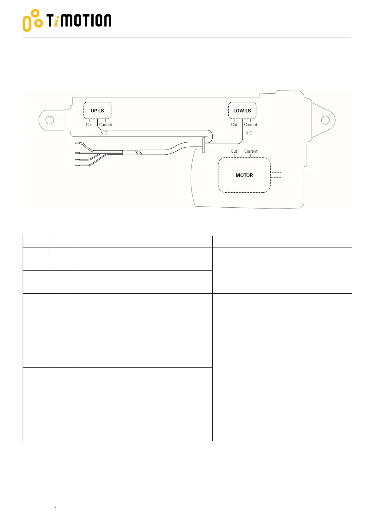
Two limit switches to cut current and send signal 2.3.4
The actuator is equipped with two limit switches to cut current of the motor and send signal when the
actuator moves to the end of each stroke.
*Please refer to section 2.3.2 for cut current module.
Connect to Vm+ to extend the actuator
Connect to Vm- to retract the actuator
24V version: Input voltage 18~32 V DC
12V version: Input voltage 9~16 V DC
Connect to Vm- to extend the actuator
Connect to Vm+ to retract the actuator
Connect to up limit switch normal closed
pin (N.O..)
The signal is NOT potential free and actively
outputs voltage at each end of stroke.
Both of the white and black signal wire are
normal open circuit when the actuator is in
the middle of stroke.
The signal circuit is connected to motor
power circuit and the value Vm+ depends
on actuator voltage.
Connect the limit switch signal wire to the
load <1A.
Connect to low limit switch normal closed
pin (N.O..)