14
E
N
G
L
I
S
H
Marker Disassembly and Assembly
Setupaworkbenchwithplentyofworkspacetomakesurenosmallpartsbecomelost.Follow
thesesafetyinstructionsatalltimeswhendisassemblingorre-assemblingyourmarker.
• FirstfollowUnloading Your Markeronpage9andAir/CO2 Supply Cylinder
Removal
instructionsonpage12.
• Alwaysweareyeprotection(likeSafetyGlasses)whenperforminganymarker
disassemblyorre-assembly.
• Donotpressurizeapartiallyassembledpaintballmarker.
• Putthemarkerintotheuncockedposition.Ifyourmarkeriscocked,holdontothe
cockingknob,pulltheTrigger,andslowlyreleasethecockingknobforwardto
uncockthemarker.
Disassemblyinstructionsarelistedhere.Tore-assemble,dothestepsinthereverseorder.
RefertothePartsDiagramonpages18and19.Itemnumbersofpartsareinparenthesis.
Barrel and Feed Tube Removal
1. RemovetheBarrel(68),byunscrewingtheBarrelfromthemarker.Toreinstallit,turnit
clockwisetothreaditintothemarker.
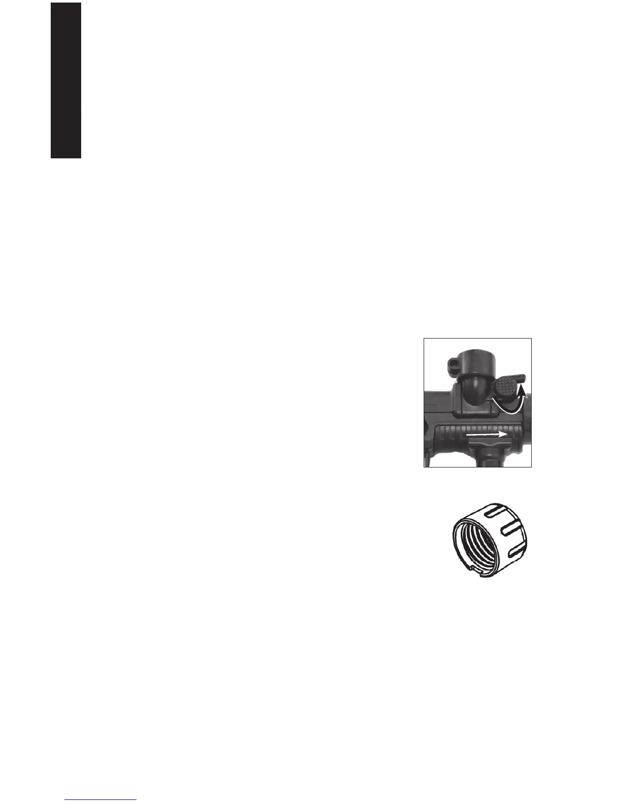
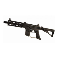
2. TheFeed Tube(4)canberemovedfromthemarker.Onthe
rightsideofthemarker,rotatetheFeedTubeLocklever(see
arrowinFig.7)untilitishorizontal.PullstraightupontheFeed
TubetoremoveitfromtheTop Receiver(1).
Make Feed Tube Permanent (optional)
a. IfitisdesiredthattheFeedTubebepermanentlylocked
tothemarker,removethescrew(item11intheassembly
diagramonpage18).
b. Removetheplasticwasher,item72,andreassemblethe
screwtothenut(10).
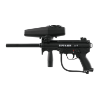
3. LookatthebottomoftheBarrel Nut(69)andidentifythecutout
area.PushinthebuttonwhilerotatingtheBarrelNutonefullturn
counterclockwise(asviewedfromthebarrelendofthemarker.
4. RotatetheBarrelNutcounterclockwise(asviewedfromthebarrel
endofthemarker)untilitisloosefromthemarker.SettheBarrel
Nutaside.
Front Grip and Ball Latch
ToreplacetheBall Latch(16),slidetheFront Grip(65)offofthemarker.TheBallLatch
shoulddropfromthemarkerontotheworkbench.
Figure8:BarrelNut
Figure7:FeedTubeand
FrontGrip
4
65