15
E
N
G
L
I
S
H
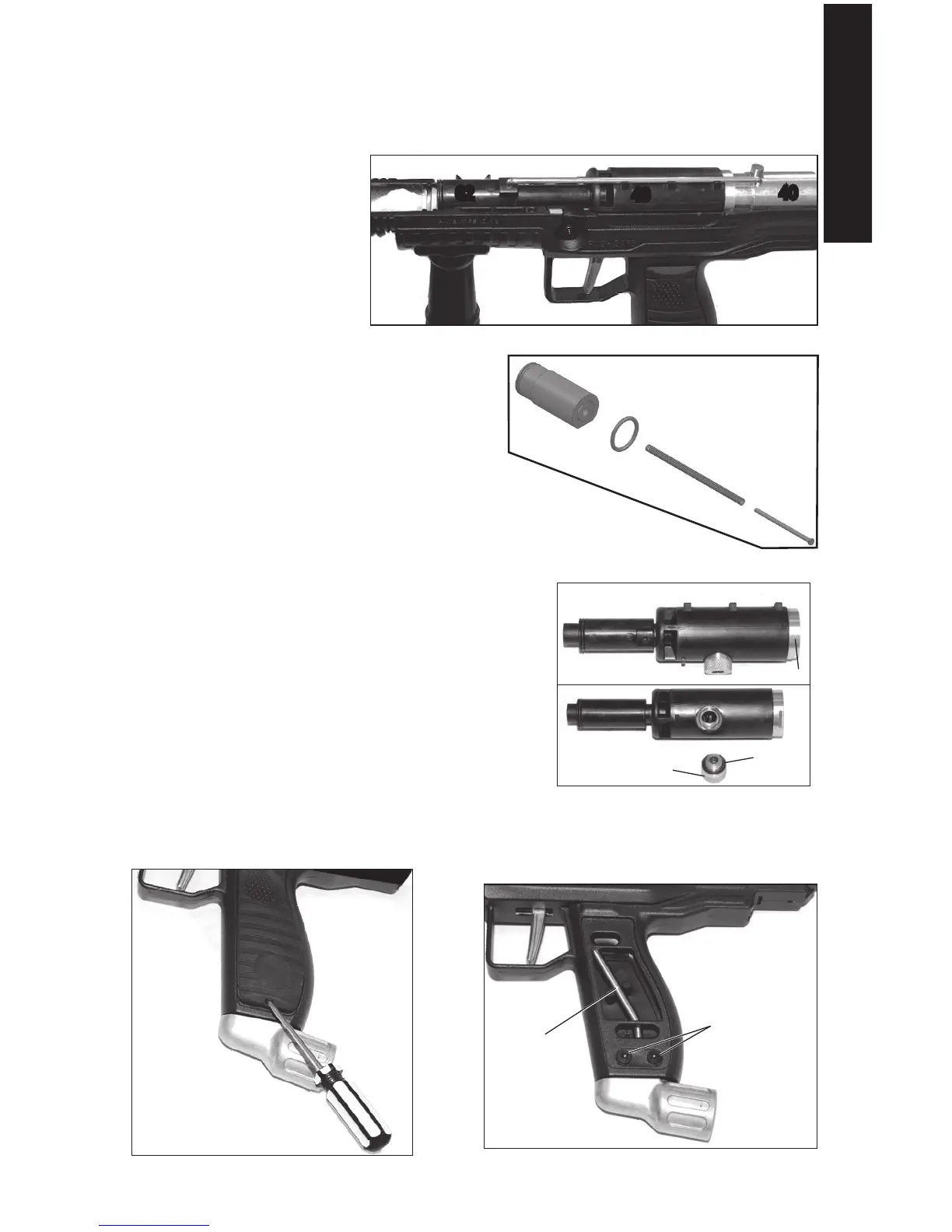
Internal Components
1. RaisethebarrelendoftheTopReceiver(itishingedattherearendoftheTop
Receiver).TherearhingecomesapartsoyoucansettheTopReceiveraside.The
markernowlookslikeFigure9.
2. LifttheLinkage Arm
(64)fromtheFront Bolt
(62)andtheRear Bolt
(40).Forre-assembly,
makesuretheLinkage
Armtsintotheguides
onthePower Tube(49)
3. SlidetheFrontBoltoffof
thePowerTube.Liftthe
Guide Pin(45),O-Ring(43),andSpring
(46)fromtherecessedareaattherearof
themarker.LifttheRear Bolt(40)fromthe
marker.
4. CAREFULLYlifttheFrontBoltandPower
Tube/ValveBodyassemblystraightupfromtheinternal
Gas Line(59).
5. TheGas Line Joint(60)unscrewsfromthePower Tube(49).Theknurled
edgeallowsyoutouseyourngerstoloosenandtighten(forre-assembly)thispart.
InspecttheO-Ring(58)fordamage,andreplace
ifdamagedorworn.
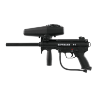
Air Supply Adapter (ASA)
1. Placeaattipscrewdriverintotheslotatthe
bottomoftheLeft Grip Cover(20)andgently
pryupwardstoremovethegripcover.
2. RemovetwoASA Screws(18)andsetaside.
3. PullstraightdownontheASA(19)toremoveit
fromtheBottom Receiver(2).
4. TheGasLinecanberemovedbypullingitstraightdownfromtheBottomReceiver.
40
43
46
45
Figure10:RemoveRearBolt
Figure9:FrontBolt,LinkageArm,PowerTube,andRearBolt
40
64
62
49
Figure11:TheFrontBoltandPowerTube/
ValveBodyAssembly
60
58
49
62
48
Figure12:RemoveLeftGripCover
20
Figure13:AirSupplyAdapterandGasLineAssembly
19
18
59
2