©TitanToolInc.Allrightsreserved. 3
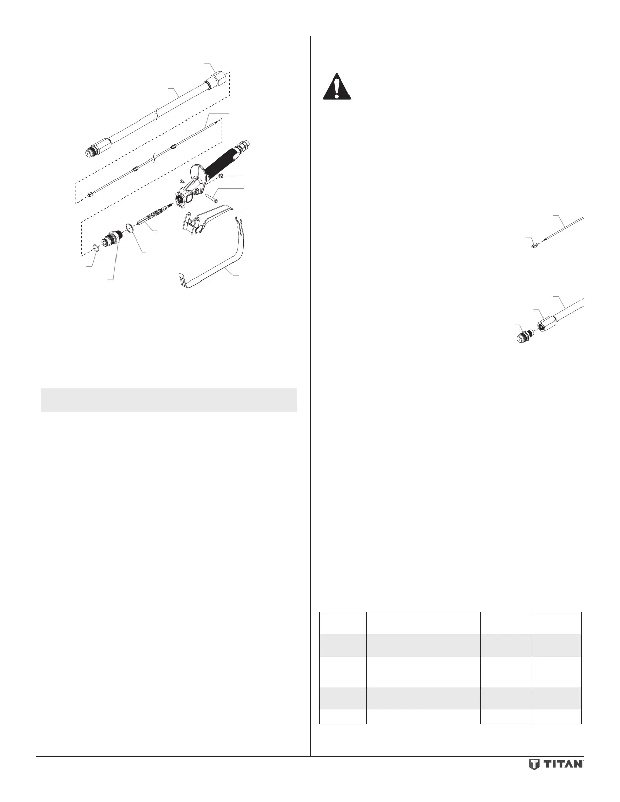
6. Removethetwotriggerscrewsthatsecurethetriggertothegun
head.Removethetrigger.
Shaft
Lock Nut
Trigger Scre
Trigger
Trigger Guard
Seal
Assembly
Seal
Washer
Extension Pole
O-Ring
ittiing
7. Placethegunheadinaviseandremovethegunheadtting.
8. Usinga3/8”socket,removethelocknutfromthethreadedendofthe
sealassemblyinsidethebackofthegunhead.
9. Usingapliers,pullthesealassemblyfromthefrontofthegunhead.
Becarefulnottodamagethethreadsinsidethegunhead.
10. Removethesealwasherfromthegunhead.
11. Soaktheremovedpartsintheappropriatesolventandwipeclean.
12. Inspectthepartsforwearordamageandusenewpartsduring
reassemblyofthegun,whennecessary.
NOTE: Lubricate all packings and moving parts with a lithium-
based grease before reassembly.
13. Installthenewsealassemblyintothefrontofthegunhead.Make
surethethreadedportionofthesealassemblyisalignedwiththe
rectangularholeinthebackofthegunhead.
14. Threadthelocknutontothethreadedshaftofthesealassemblyin
thebackofthegunhead.Tightenthenutuntilapproximately1/16”
ofthesealassemblyshaftsticksoutpastthenut.
15. Applyalithium-basedgreasetobothsidesofthenewsealwasherand
insert the washer into the groove inside the gun head.
16. Installthegunheadttingintothegunheadandtightenuntilthehex
onthettingmeetsthegunhead.Makesurethesealwasherremains
in the groove inside the gun head during installation. Torque to
45–50ft./lbs.
17. Reassemblethetrigger.
18. Inspecttheo-ringonthegunheadttingandreplaceifnecessary.
19. ApplyLoctitetothethreadsontheshaft.Holdthesealassemblyin
placewithawrenchandthreadtheshaftintothesealassemblyuntil
itstopsonthechamferedshoulder.Donotapplyexcessiveforceon
the shaft.
20. Lubricatetheo-ringonthegunheadttingandreassemblethe
extensionpoletothegunheadtting.Triggerthegunbeforenal
tighteningoftheextensionpoletopreventdamagetotheballholder.
21. Testtheoperationofthetrigger.Thereshouldbeasmallamountof
play in the trigger after the trigger is released. This will ensure that
theballholderisfullyseatedinthediuserandthegunisshuto
when the trigger is released. Adjust the position of the lock nut on the
sealassemblyiftriggeradjustmentisnecessary.
22. Reassemblethetriggerguard.
23. Startthesprayerandpressurizethegun(refertotheinstructionsin
thesprayer’sOwner’sManual).Checkthegunforleaks.
24. Movethetriggerlocktothelockedposition.Pullthetriggerand
check for leaks.
Replacing the Ball Holder and Diuser
Usethefollowingproceduretoreplacetheballholderanddiuseronthe
spray gun.
Never attempt to perform maintenance on the spray gun
without first performing the “Pressure Relief Procedure.”
1. Disconnecttheairlesssprayhosefromthegun.
2. Removethetipguard,tipswivel,andpolemountfromthegun.
3. Placeonewrenchonthegunheadttingandanotherwrenchonthe
rear tting of the extension pole. Turn the entire extension pole to
unthread it from the gun head tting.
IMPORTANT: Do not try to remove either of the fittings on the extension
pole. Movement of these fittings will break the factory seal and cause the
gun to leak.
4. Carefullyremovetheentireextensionpoletoexposetheshaftand
ballholder.Makesuretothesupporttheshaftduringremovalofthe
extension pole.
Shaft
Ball
Holder
5. Placealockingpliersontheshaftas
closeaspossibletotheballholder.
Whileholdingtheshaftinplacewith
thelockingpliers,unthreadtheball
holder from the shaft using a wrench.
6. ApplyLoctitetothethreadsofthe
shaftandthreadthenewballholderontotheshaftuntilitstopsat
theangledshoulderoftheshaft.Donotapplyexcessiveforceonthe
shaftorballholder.
Extension Pole
Diuser
Front Fitting
7. Placeonewrenchonthewrenchats
ofthediuserandanotherwrench
on the front tting of the extension
pole.Unthreadthediuserfromthe
extensionpole.Makesurethetting
on the extension pole does not move
duringremovalofthediuser.
8. Threadthenewdiuserintothefront
ttingoftheextensionpole.Makesuretoholdthettingonthe
extensionpolewithawrench.Torquethediuserto40-50ft./lbs.
9. Inspecttheo-ringonthegunheadttingandreplaceifnecessary.
10. Lubricatetheo-ringonthegunheadttingandreassemblethe
extensionpoletothegunheadtting.Triggerthegunbeforenal
tighteningoftheextensionpoletopreventdamagetotheballholder.
11. Testtheoperationofthetrigger.Thereshouldbeasmallamountof
play in the trigger after the trigger is released. This will ensure that
theballholderisfullyseatedinthediuserandthegunisshuto
when the trigger is released. Adjust the position of the lock nut on the
sealassemblyiftriggeradjustmentisnecessary.
12. Startthesprayerandpressurizethegun(refertotheinstructionsin
thesprayer’sOwner’sManual).Checkthegunforleaks.
13. Movethetriggerlocktothelockedposition.Pullthetriggerand
check for leaks.
Replacing/Removing the Filter
1. Pullthebackofthetriggerguarddownsothatitcomesloosefrom
theswivelassemblyonthehandle.
2. Removethehandleassemblyfromthegunhead.
3. Pulltheoldlteroutofthegunhead.
4. Pushtheneworcleanedlterintothegunhead.
5. Makesurethehandlesealisinpositionandthreadthehandle
assemblyintothegunheaduntilsecure.
6. Snapthetriggerguardbackontothehandleassembly.
Filter Chart
Part
Number
Application Filter Type Color of
Filter Body
550-486 Syntheticresin,enamels,clean
varnishes,stains,azures
Extrane red
550-485 Basecoatenamels,primer
enamels,llers,markingpaints,
textured enamels
Fine yellow
550-483 Emulsions,latexpaints,acrylic
paints
Medium white
550-484 Fillerpaints,largeareasurfaces Coarse green
 Loading...