EN
31
In more detail...
EN
Care and maintenance
NOTE: The planning surface will end up rough and uneven unless the
blades are set properly and securely. The blades must be mounted so
that the cutting edge is absolutely level, e.g. parallel to the surface of
the back plate.
The following examples show proper and improper settings:
Fig. A – Clean smooth cut.
Fig. B – Nicks in surface – as caused by the edge of one or all blades not being
parallel to the rear base line.
Fig. C – Gouging at start – as caused by the edge of one or all blades not
protruding enough in relation to the rear base line.
Fig. D – Gouging at end – as caused by the edge of one or all blades protruding
too far in relation to the rear base line.
A
a
b
B C D
a
b
a
b
(a) = Adjustable front plate (28), (b) = Fixed back plate (25)
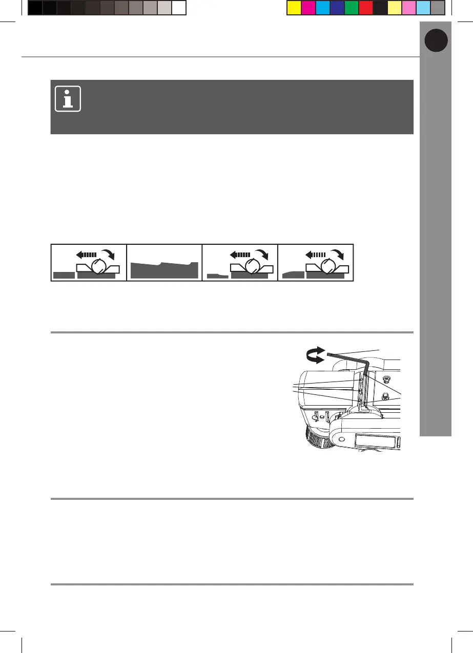
Cutter block
The height is pre-set in the factory and normally
there is no need to re-adjust. Nevertheless check
whether the front plate (28) runs parallel to the
roller edge occasionally. If necessary adjust the
height with the hex key (29) (Fig. 18).
1. Loosen the hex bolts (20).
2. Turn the grub screws (22) clockwise to
increase the height.
3. Turn the grub screws (22) anticlockwise to
decrease the height.
20
29
22
+
-
Fig. 18
Maintenance
Before and after each use, check the product and accessories (or attachments)
for wear and damage. If required, exchange them for new ones as described in
this instruction manual. Observe the technical requirements.
Power cord
If the supply cord is damaged, it must be replaced by a specially prepared cord
available through the service organization.
TTB876PLN by TITAN
 Loading...