Hardware Version : 5.02 Document Version : 1.0.
TECHMAN ROBOT INC. 5F., No. 58-2, Huaya 2nd Rd., Guishan Dist., Taoyuan City, 333411 , Taiwan
30
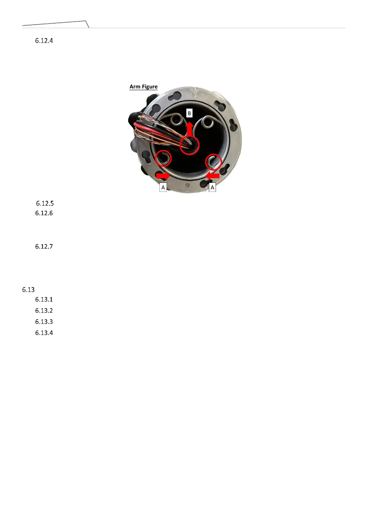
(Please refer Arm figure below) After removing the Upper arm, use needle-nose pliers to compress the
bracket at location A, then extract the bracket from the groove. Next, remove the wiring and plastic bushing at
location B.
During Lower arm assembly, follow the reverse steps of the previously mentioned procedure.
When replacing the MII cable, camera cable, and S48V cable from Joint 4 to Joint 5, there is no need to
disassemble the Arm tube. You can directly insert the new cables from Joint 5 and pull them out from Joint 4.
For the old cables, trim the connectors at both ends and pull them out.
When inserting the new cables, apart from the power cable, the other cables (MII cable, camera cable,
S48V cable) do not need to be tied inside the metal ring. However, it is necessary to use acetic acid cloth to
secure the new cables.
Disassembly and assembly End module
Remove Joint cover and Joint rubber which in Joint 6
Remove Joint cable which in Joint 6.
Remove the connecting screws between Joint 6 and the End module, then detach the End module.
During assembly, follow the reverse steps of the previously mentioned procedure.