ARTICULATED ARM OPENERS USER MANUAL
10
2.3 SYSTEM LEARNING PROCESS
Step1: Connect the master motor wires to M1 terminals and the slave motor wires to M2 terminals correctly. If only
one gate is installed, the motor wires have to be connected to M1 terminals.
Step2: Set the function F2-1 for double gate learn; or set the function F2-2 for sigle gate learning.
Step3: Press and hold the “UP+SET+DOWN” button on the PCB for 3 seconds. After LED1 blinks once per second,
press the button on the transmitter to choose dual-gate(A button) or single-gate(B button) system learning.
In system learning mode, the gates will proceed with the following procedures.
Step4: When changing F2 setting, it is required to do the system learning process again.
(A) Dual-Gate Mode: Slave Gate closes→Master Gate closes→Master Gate opens→Slave Gate opens→Slave
Gate closes→Master Gate closes.
(B) Single-Gate Mode: Master Gate closes→Master Gate opens→Master Gate closes.
The completion of system learning:
(A) For Dual-Gate installation: The system learning is completed when LED1 quickly blinks twice per second.
(B) For Single-Gate installation: The system learning is completed when LED1 quickly blinks once per second.
Notes:
(A) System learning fails and needs to be learned again when an unpredictable interruption occurs.
(B) Once the system learning is completed, there is no need to proceed with the learning process again when
there isa power failure.
(C) The slave gate opens 3 seconds after the master gate opens and the master gate closes 3 seconds after the
slave gate closes.
(D) While using limit switch mode, please make sure the motor hit limit switch when it’s in deceleration speed.
2.2 TRANSMITTER MEMORIZING AND ERASING PROCESS
(A) Transmitter Memorizing: Press and hold the “RF-LEARN” button on the PCB for 1 second and then the blue LED
indicator on the RF board will be “ON”. Press A button for dual-gate installation ; press B button for single-gate
installation on the transmitter within 5 seconds. The transmitter learning is completed
when the blue indicator is “OFF”.
(B) Transmitter Memory Erasing: Press and hold the “RF-LEARN” button on the PCB for 10 seconds until blue LED off.
(C) One radio receiver can be memorized with 200pcs of transmitters.
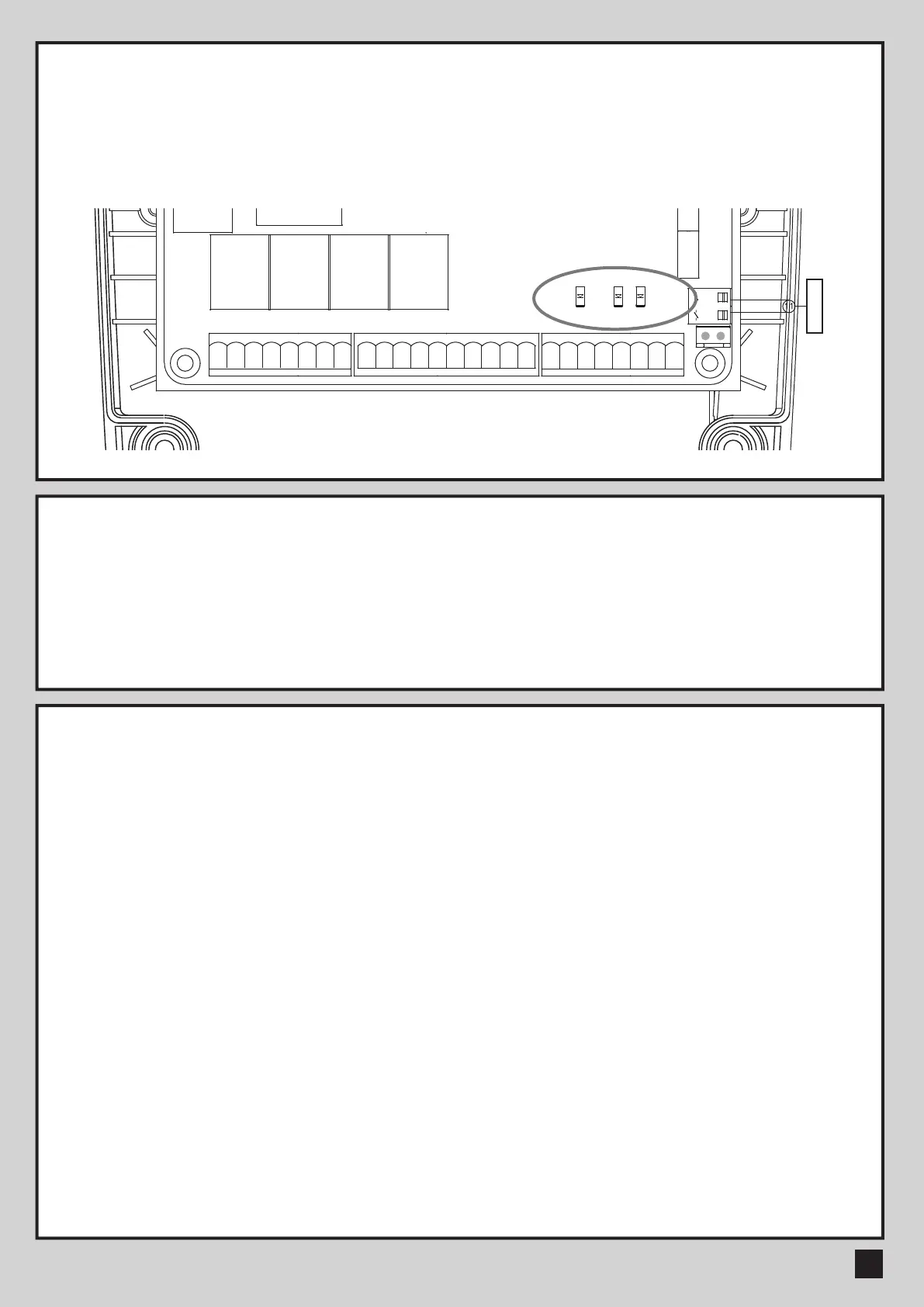
LED1 System Learning: blue LED1 in receiver board blinks three times when learning is completed.
LED2 RF : If the switch of the transmitter, key selector, or the push button is activated, LED2 will be on.
LED3 Photocells 1 : LED3 will be on when the first pair of the photocells are activated.
LED4 Photocells 2 : LED4 will be on when the second pair of the photocells are activated.
Antenna
M2-M1-
Lat-
Lit-
Lmt4Lmt3
Lmt2
Lit+ SKey
S1
M2+
M1+Lat+ Ph2Ph1 PhVcc PhVcc
S25V
ANT
GND
DKey GND
GND
GND
GND
Lmt1
GND
CB19-PCB1
40121-377-A1
T4
SW3
UP
Q17
J5
SW1
RF-LEARN
RF1
K5
K3
K2K1
J4 J3
J7
F1
DB1
J8
SW4
SET
SW5
DOWN
NC NO
CO
+-
NC NO
CO
+-- +
CO
NONC
- +
CO
NONC
NC NO
CO
+-
-
+
1 2 3 4 5 6 7 8
9 10 11 12 13 14 15 16 17 18
19 20 21 22 23 24 25 26
LED2
LED3
LED4
2.1 LED INDICATION
 Loading...