A
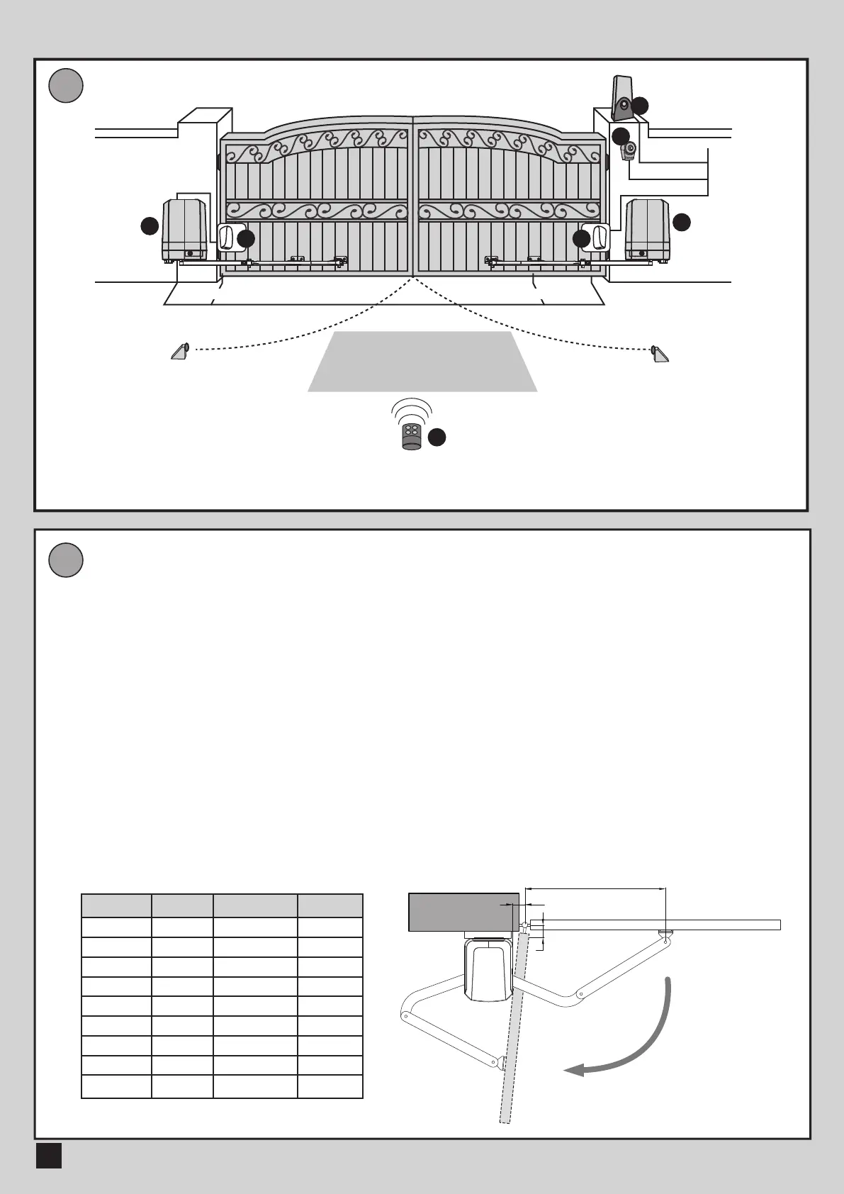
STANDARD INSTALLATION
B
DIMENSION CHART
ARTICULATED ARM OPENERS USER MANUAL
2
1.2 INSTALLATION
2x1.5 mm
2
4x0.5 mm
2
TX - 4x0.5 mm
2
RX - 4x0.5 mm
2
2x1.5 mm
2
2x1.5 mm
2
Please comply with the measures shown on the chart for proper installation. If necessary,
please adjust the gate structure to the best operation.
Before starting the installation, please make sure that the gate moves freely and that :
1) Hinges are properly positioned and greased.
2) No any obstacle in the moving area.
3) No frictions between two gate leafs or and on the ground while moving.
4) To leave enough space when the gate is opening.
a. Distance between the bolt and horizontal wall surface.
b. Distance from the bolt perpendicular to the surface of articulated arm opener.
c. Distance between the position of arm fixation and the bolt.
d. Installation angle from full closed and full opened position.
4
4
2
33
1
5
1. 24V DC blinker with integrated antenna
2. Push Button
3. Photocells
4. 24V DC articulated arm opener
5. TM3 Transmitter
A(mm)
50
50
50
100
100
100
150
150
150
B(mm)
50
100
150
50
100
150
50
100
150
C(mm)
450~650
380~640
360~620
390~600
370~590
360~580
450~600
510~590
500~580
D
90
o
90
o
90
o
90
o
90
o
90
o
100
o
100
o
100
o
A
D
C
B
 Loading...