ARTICULATED ARM OPENERS USER MANUAL
4
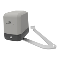
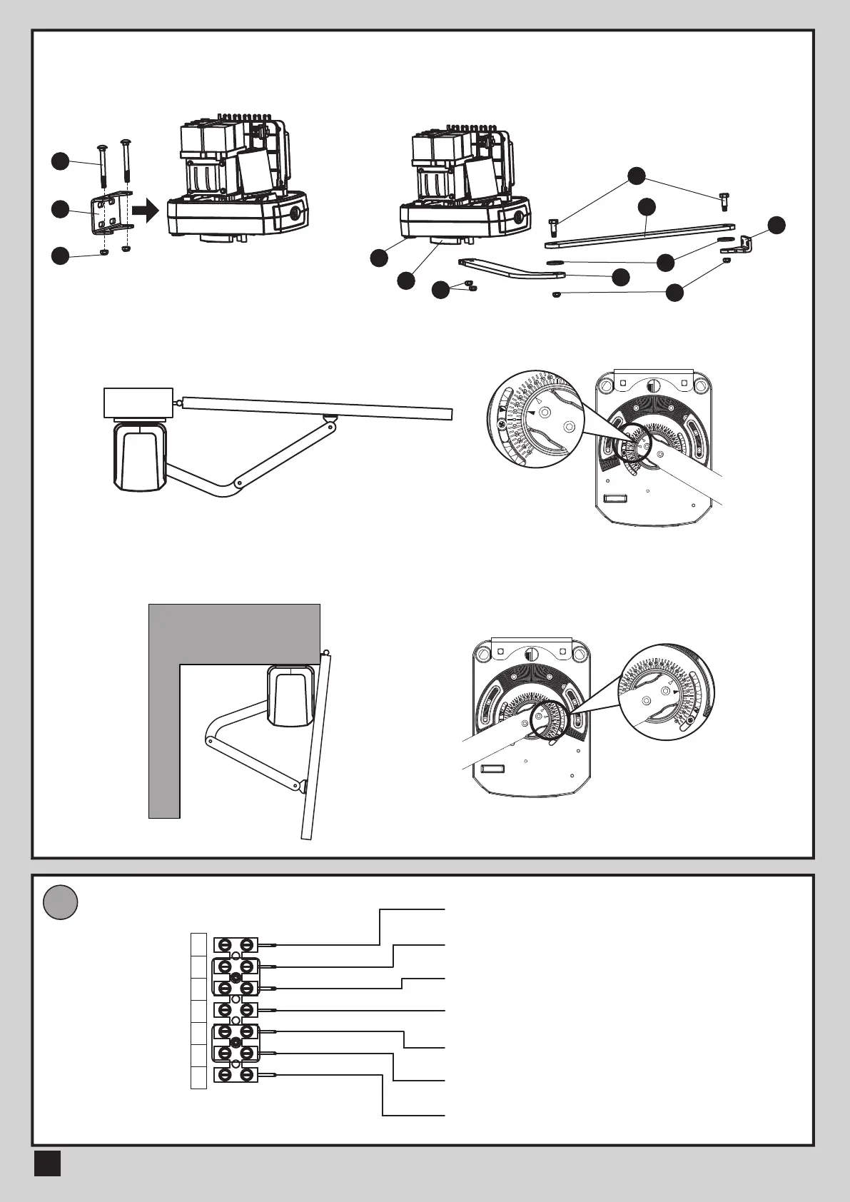
4) After positioning the front of curved arm on the bottom of motor,
release the motor and position the minor arm on the end of
curved arm and mounting bracket with corresponding screws
and nuts.
5) Closed position adjustment :
4.1 After the full closed position decided, fix the corresponding mechanical stopper at the position.
4.2 After the full closed position decided, make the pointer on limit switch aligned with the pointer on the curved arm.
(Red points shown on the figure below indicate the pointers)
6) Opened position adjustment :
5.1 Adjust the gate to full opened position and after the position decided, fixed with corresponding mechanical stopper.
5.2 Adjust the gate to full opened position and after the position decided, make the pointer on the electromechanical
limit switch aligned with the pointer on the curved arm. (Red points shown on the figure below indicate the pointers)
WIRE CONNECTION
E
White (+)
Yellow (-) Motor
Red (5V)
White (Signal)
Black (GND)
Blue (Left-side electromechanical limit switch)
Green (Right-side electromechanical limit switch)
1
5
2
4
13
7
3
8
12
3) Install the motor on the U-shaped fixing
plate with corresponding screws and nuts.
White
+
Yellow
-
Red
5V
Green
Signal
Black
(GND)
Blue
Limit 1
Gray
Limit 2
12
9
10
 Loading...