40
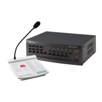
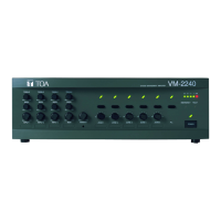
23.2. VM Amplifier's Internal Function Switches
The switches must be set by a qualified service technician only.
Each of the following functions can be selectively set with the switches.
For the switch setting method, refer to the separate instruction manual for qualified service technicians.
Priority levels (Underlined priority levels represent factory-preset levels.)
Priority modes, Unit type, and Number of units (Underlined settings represent factory-preset settings.)
BGM broadcast volume attenaution level (Underlined level represents factory-preset level.)
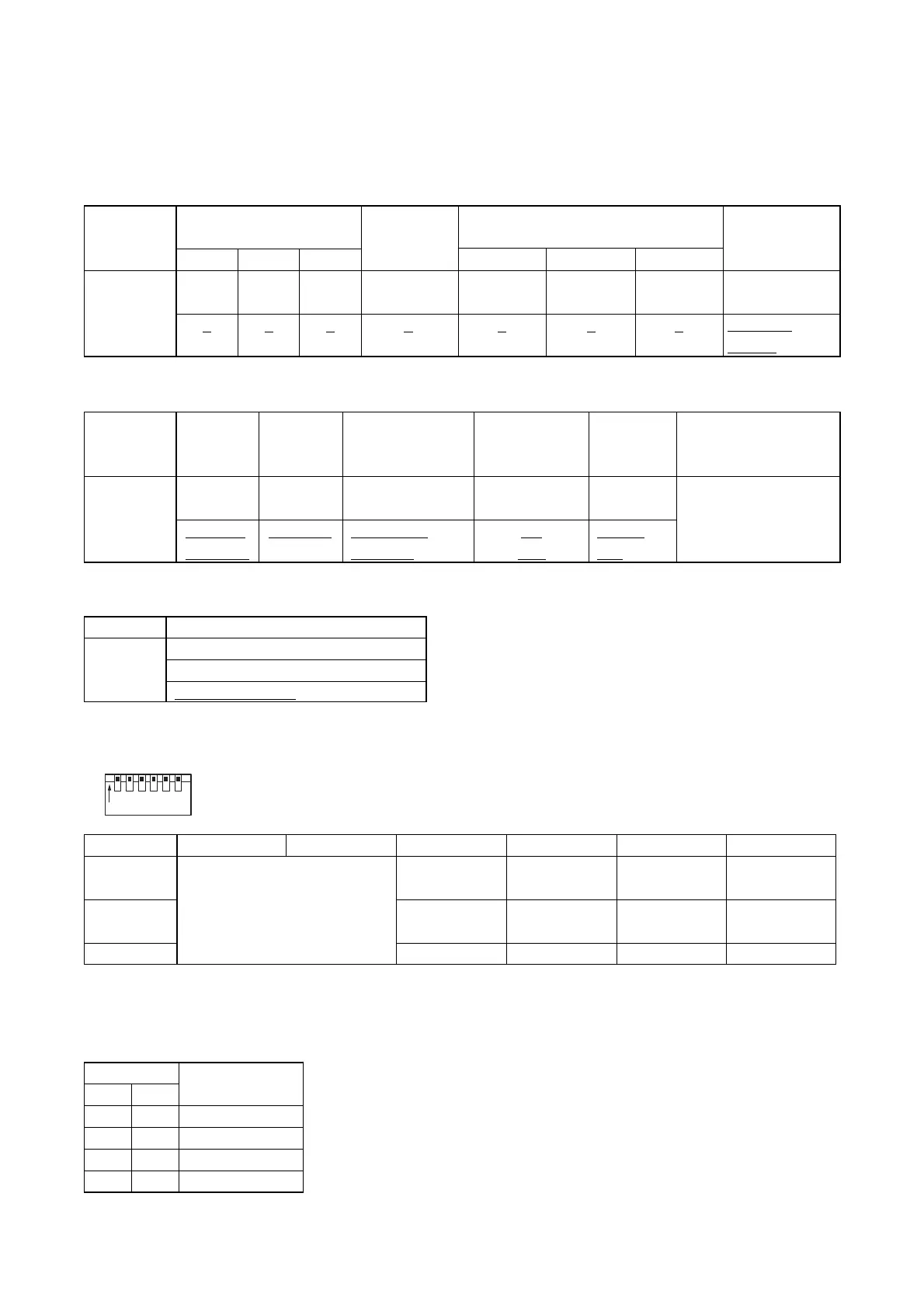
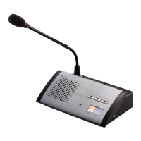
23.3. Remote Microphone's Function Switches
* One of 2 priorities can be set for each Remote microphone. (See p.26 "GENERAL-PURPOSE
BROADCAST PRIORITY.")
RM (RM-200M) Unit No. table
All switches No. 1 – 6 are factory-preset to the ON position.
6
Compressor
On
Off
The switch is actually installed upside down.
Switch No.
Function
ON
OFF
12
RM Unit No.
(See the RM Unit No.
table below.)
3
Broadcast
Priority*
2
1
4
Talk key
operation
Press-to-talk
type
Talk lock type
5
Emergency
switch
Enable
Disable
RM Unit No.
No. 1
No. 2
No. 3
No. 4
Switch No.
12
ON ON
OFF ON
ON OFF
OFF OFF
Function
Input 1 Input 2 Input 3 Message 3 Message 4 Message 5
1 1 1 1 3 3 3
Selectable
2
2 2 2 1 1 1
Priority Mode
for Same
Priority Unit
Unit No. Priority
(Numerical order)
First/Last
Priority
Inputs 1 – 3
Broadcast Priority Level
Voice Announcement Board's
Message Priority Level
TEL Paging
Priority Level
Function
Mixed Silent On Sub-unit
Selectable
(off)
Off
(on)
First/Last
Priority
First-come
first-served
Last-come
first-served
Not mixed
Evacuation
message
Master
unit
Priority 2
Mixing
Mode after
Emergency Talk
Input 3/LINE
(Input 3/MIC)
Chime On/Off
Unit Type No. of Connected
Units
0 through 5
Function BGM broadcast volume attenuation
No attenuation
Selectable –28 dB (just audible)
–∞ dB (inaudible)