EasyManua.ls Logo

Toa VM-2120 User Manual

Toa VM-2120
60 pages
To Next Page IconTo Next Page
Page #1 background imageLoading...
Page #1 background image
INSTRUCTION MANUAL
SYSTEM MANAGEMENT AMPLIFIER
REMOTE MICROPHONE
REMOTE MICROPHONE EXTENSION
VOICE ANNOUNCEMENT BOARD
SURVEILLANCE BOARD
VM-2120 (120 W)
VM-2240 (240 W)
RM-200M
RM-210
EV-200M
SV-200MA
VM-2120
RM-200M
Please follow the instructions in this manual to obtain the optimum results from this unit.
We also recommend that you keep this manual handy for future reference.

Table of Contents

Other manuals for Toa VM-2120

Question and Answer IconNeed help?

Do you have a question about the Toa VM-2120 and is the answer not in the manual?

Toa VM-2120 Specifications

General IconGeneral
BrandToa
ModelVM-2120
CategoryConference System
LanguageEnglish

Summary

SAFETY PRECAUTIONS

Safety Symbols and Message Conventions

Explains symbols and messages used for safety warnings.

Installation Precautions

Guidelines for safely installing the unit to prevent damage or injury.

Usage Precautions

Important safety measures to follow when operating the unit.

GENERAL DESCRIPTION

System Management Amplifier VM-2120/VM-2240

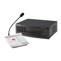
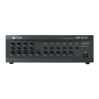
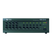
Overview of the main amplifier's features and applications.

Remote Microphone RM-200M

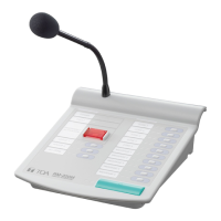
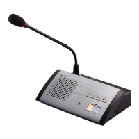
Description of the dedicated remote microphone unit.

Remote Microphone Extension RM-210

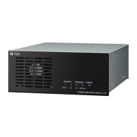
Description of the extension unit for the remote microphone.

FEATURES

HANDLING PRECAUTIONS

INSTALLATION PRECAUTIONS

VM Amplifier Front Panel Nomenclature

VM Amplifier Rear Panel Nomenclature

EV-200M Board Nomenclature

SV-200MA Board Nomenclature

RM-200M Remote Microphone Nomenclature

RM-210 Remote Microphone Extension Nomenclature

SYSTEM CONFIGURATIONS

Remote Microphone/VM Amplifier Configuration

How to set up the number of connected units in the system.

Remote Microphone Operation Panel Function

Explains how zone/message selectors work based on amplifier configuration.

Connection between Remote Microphone and VM Amplifier

Details connection methods and cable requirements between units.

VM Amplifier Power Supply to Remote Microphone

How the VM amplifier supplies power to remote microphones.

EMERGENCY BROADCAST

Emergency Broadcast System Equipment

Outlines the components involved in the emergency broadcast system.

Emergency Broadcast Keys and Indicators

Identifies relevant keys and indicators for emergency operations.

Typical Emergency Broadcast Operation

Provides a step-by-step guide for alert and evacuation broadcasts.

Emergency Broadcast Sequence

Illustrates the flow of events during an emergency broadcast.

BROADCAST OPERATION AT THE AMPLIFIER

Amplifier Microphone Announcements (Control Input)

How to perform microphone announcements using control inputs.

Amplifier Background Music Broadcast

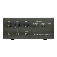
Steps for broadcasting background music from the amplifier.

REMOTE MICROPHONE GENERAL-PURPOSE BROADCAST

Operation and Display Sections

Overview of the remote microphone's operational panel sections.

Remote Microphone Broadcast Operation Types

Describes how to make All-Zone, Zone, Group, and Message broadcasts.

BROADCAST PRIORITY MANAGEMENT

Broadcast Source Priority Levels

Explains how different broadcast sources are prioritized.

Priority Between Equal Level Broadcasts

Details priority modes when broadcasts have the same priority level.

Priority Function During BGM Broadcast

How other broadcasts affect background music (BGM) broadcast.

CHIME FUNCTIONALITY

Available Chime Tone Types

Lists the different types of chime tones available for broadcasts.

Chime Tone Usage Scenarios

Explains the usage scenarios for chime tones in various inputs.

Independent Chime Activation (Remote Control)

Describes how to activate chime tones remotely via control signals.

CHOKE COIL INSTALLATION

INPUT TRANSFORMER INSTALLATION AND BOARD MODIFICATION

MOUNTING OPTIONAL EV-200M VOICE ANNOUNCEMENT BOARD

MOUNTING OPTIONAL SV-200MA SURVEILLANCE BOARD

RACK MOUNTING

AMPLIFIER INPUT CONNECTION

Two Amplifiers Stack-Connection

How to connect two VM amplifiers in a stack configuration.

Microphone Connection to the VM Amplifier

Details on connecting microphones, including DIN and XLR types.

Telephone Paging Input Connections

Wiring instructions for connecting a telephone paging system.

EXTERNAL ATTENUATOR CONTROL WIRING

External Attenuator 4-Wire System Connection

Wiring diagram for a 4-wire system controlling external attenuators.

External Attenuator 3-Wire System Connection

Wiring diagram for a 3-wire system controlling external attenuators.

CHANGING THE SPEAKER LINE VOLTAGE

CONTROL I/O CONNECTOR FUNCTIONS

SURVEILLANCE I/O CONNECTOR FUNCTIONS

FUNCTION SWITCH SETTINGS

VM Amplifier Rear Panel Switch Settings

Guide to setting the rear panel SETTINGS switches (No. 1-8).

VM Amplifier Internal Switch Settings

Information on internal switches for priority and mixing settings.

RM-200M Function Switch Settings

Details on setting the function switches on the RM-200M.

BROADCAST GROUP AND ZONE SETTING

Broadcast Routing Assignment

Assigning broadcast zones to groups for organized broadcasts.

Control Input/Paging to Group Assignment

Assigning control inputs/paging to specific broadcast groups.

Recorded Message to Group Assignment

Assigning recorded messages to specific broadcast groups.

OPERATING KEYS AND ASSIGNMENT OPERATIONS

Zone-to-Group Assignment Operation

Step-by-step guide for assigning zones to broadcast groups.

Control Input/Paging-to-Group Assignment Operation

Procedure for assigning control inputs/paging to groups.

Recorded Message-to-Group Assignment Operation

How to assign recorded messages to broadcast groups.

REMOTE MICROPHONE AND EXTENSION LINKAGE

NAME LABEL PREPARATION GUIDE

Amplifier Name Label Preparation

Guidance on preparing and affixing labels for amplifier controls.

Remote Microphone Name Label Preparation

Instructions for preparing and inserting labels for remote microphones.

COMPACTFLASH CARD RECORDING

CF Card Recording Procedures

Steps for using the EV-350R for CF card recording.

Message Program Composition Example

Examples of composing messages and programs for the CF card.

Message Program Operation Example

Illustrates how message programs operate.

BLOCK DIAGRAM

VM-2120/-2240 SPECIFICATIONS

RM-200M SPECIFICATIONS

RM-210 SPECIFICATIONS

EV-200M SPECIFICATIONS

SV-200MA SPECIFICATIONS

Related product manuals