Do you have a question about the Toa RM-200M and is the answer not in the manual?
Illustrates a basic system ideal for facilities not requiring a FACP.
Shows a system for large stores, connecting to FACP and MNS-Strobe.
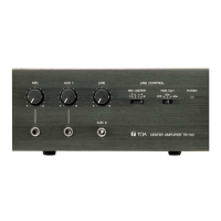
Details the central unit's role, power, and connectivity.
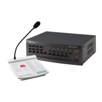
Explains system expansion with VM-3240E and its features.
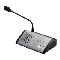
Describes the RM-200M microphone's connectivity and function.
Covers BGM and microphone announcements via the VM-3240VA.
Explains microphone and automatic announcements using the RM-200M.
Details how to trigger broadcasts via external control signals.
Provides a procedural overview for various general broadcast methods.
Guides on using the VM-3240VA for microphone and auto emergency broadcasts.
Outlines the steps for initiating and terminating emergency broadcasts.
Explains priority levels for different sound sources in general broadcasts.
Details the fixed priority order for emergency announcements.
Explains the function for making all-zone calls during system failures.
Describes how to perform all-zone calls when the CPU is off.
Defines the system monitoring function for operating conditions and faults.
Provides steps to initialize and set up the surveillance function.
Lists the system components that are monitored by the surveillance function.
Outlines actions for failure detection, acknowledgment, and reset.
Lists and explains various failure messages displayed on the VM-3240VA's LCD.
Identifies the keys on the VM-3240VA front panel used for settings.
Visualizes the navigation path for various system settings.
Covers password, date/time, network, log, and data transfer settings.
Details language selection and version information display.
Covers adjustments for input tone, BGM volume, chime, and announcement volumes.
Explains how to initialize and configure the surveillance function.
Details LINE/MIC selection, phantom power, and tone settings for Inputs 1-3.
Covers BGM selection, treble, and bass adjustments.
Explains the functions assigned to the DIP switches on the RM-200M.
Details how to set the unit ID using DIP switches 1 and 2.
Describes the PTT and Lock modes for the Talk key operation.
Explains how to enable/disable compression using DIP switch 6.
Provides instructions for wall mounting the RM-200M.
Guides on printing and inserting name labels for function keys.
Details precautions and procedures for mounting equipment in a rack.
Explains wiring procedures for removable terminal plugs.
Illustrates typical audio and control signal connections.
Shows how to connect the system to a Fire Alarm Control Panel.
Details power supply and link connections for RM-200M.
Explains functions assigned to general control inputs.
Lists functions assignable to emergency control input terminals.
Describes relay contact outputs for CPU OFF, failure, and emergency status.
Illustrates the connection of a NAC Extender to the system.
Shows FACP and NAC Extender connections when MNS has higher priority.
Shows FACP and NAC Extender connections when MNS has lower priority.
Illustrates the connection of FACP, NAC Extender, and UPS.
Details how to connect speakers to the power amplifier outputs.
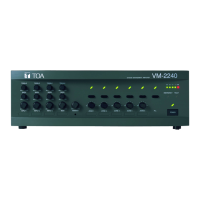
Explains how to connect multiple VM amplifiers using DIP switches for ID.
Guides on connecting power supply units like VX-2000DS and batteries.
Specifies the number of VX-2000DS units required per VM amplifiers.
Provides detailed technical specifications for the VM-3240VA amplifier.
Lists detailed technical specifications for the VM-3240E extension amplifier.
Details the technical specifications for the RM-200M remote microphone.
| Type | Remote Microphone |
|---|---|
| Output Impedance | 600 Ω, balanced |
| Microphone Element | Electret condenser microphone |
| Directivity | Unidirectional |
| Power Supply/Source | 24 V DC (supplied from the central unit) |
| Finish | ABS resin, black |
| Operating Temperature | 0°C to +40°C |
| Sensitivity | -37 dB ±3 dB (0 dB=1 V/Pa at 1 kHz) |