EasyManua.ls Logo

Toa RM-200M - External Emergency Control Equipment Connection

Toa RM-200M
105 pages
Print Icon
To Next Page IconTo Next Page
To Previous Page IconTo Previous Page
Loading...
85
VM-3240VA rear
CTRL IN 1
COM 1
CTRL IN 2
COM 3
CTRL IN 3
COM 2
CTRL IN 4
COM 4
NC
CTRL IN 5
COM 5
Not used
Not used
Not used
Not used
CTRL IN 6
COM 6
NC
Emergency control
input terminals 1 – 4
Emergency control
input terminals 5 and 6
Contact
control
Voltage
control
Shield
Orange/White
Orange
Green/White
Blue
Blue/White
Green
Brown/White
Brown
Green/White
Green
Orange/White
Blue
Blue/White
Orange
Brown/White
Brown
Connector name Pair Assignment
RJ45 connector
pin No.
Cable color
(T568B type)
Cable color
(T568A type)
Shield
Orange/White
Orange
Green/White
Blue
Blue/White
Green
Brown/White
Brown
CTRL IN 1 – 4
CTRL IN 5 – 6
Green/White
Green
Orange/White
Blue
Blue/White
Orange
Brown/White
Brown
RJ45 connector
Pin No.
1
2
5
4
3
6
7
8
RJ45 connector
Pin No.
1
2
5
4
3
6
7
8
CTRL IN 1
Fire Alarm
COM 1
1
2
3
4
CTRL IN 2
COM 2
CTRL IN 3
COM 3
CTRL IN 4
COM 4
CTRL IN 5
COM 5
24 V
CTRL IN 6
COM 6
Emergency Reset
switch
[Terminal assignment to the emergency control inputs]
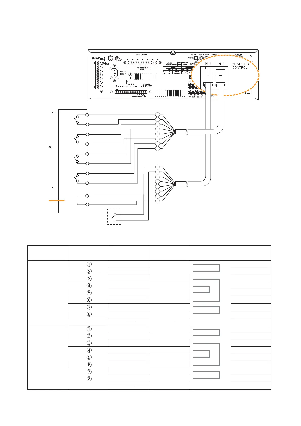
13.5.1. External emergency control equipment connection
Note
Contact inputs 1 – 5 are no-voltage
make contact inputs. Input 6 is an
isolated voltage input which is
activated when the polarity of the
applied voltage (24 V DC is kept
applied to this terminal under
normal condition) is reversed.

Table of Contents

Other manuals for Toa RM-200M

Related product manuals