Do you have a question about the Toa EV-200M and is the answer not in the manual?
Provides safety guidelines for installing applicable models, VM-2120/-2240, and RM-200M/-210.
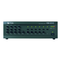
Details the front panel layout and functions of the VM-2120/-2240 amplifier.
Details the rear panel layout and functions of the VM-2120/-2240 amplifier.
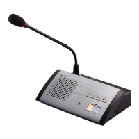
Details the top panel layout and functions of the RM-200M remote microphone.
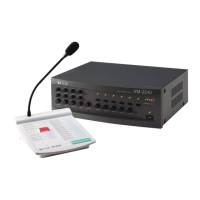
Outlines the equipment setup for emergency broadcast systems.
Identifies key controls and indicators on amplifier/mic for emergency broadcasts.
Details terminating emergency broadcasts and operational notes.
Illustrates the sequence of events during emergency broadcasts and restoration.
Details the operation and display sections of the RM-200M remote microphone.
Explains end of broadcast procedures for press-to-talk and lock operation modes.
Guides on setting rear panel switches for phantom power, paging chime, chime selection, and input gain.
Details internal switches for priority levels, mixing modes, and BGM attenuation.
Guides on assigning recorded messages to broadcast groups.
Continues zone-to-group assignment operation, including all zones setting.
Continues assignment operation, explaining group selection and dual indications.
Explains the operation for assigning recorded messages to broadcast groups.
Explains combining broadcast zones into groups for broadcasting.
Identifies and describes the function of various operating keys on the VM amplifier.
Details assigning control inputs and telephone paging to broadcast groups.
Lists final specifications, dimensions, weight, and accessories.
| Brand | Toa |
|---|---|
| Model | EV-200M |
| Category | Conference System |
| Language | English |