10
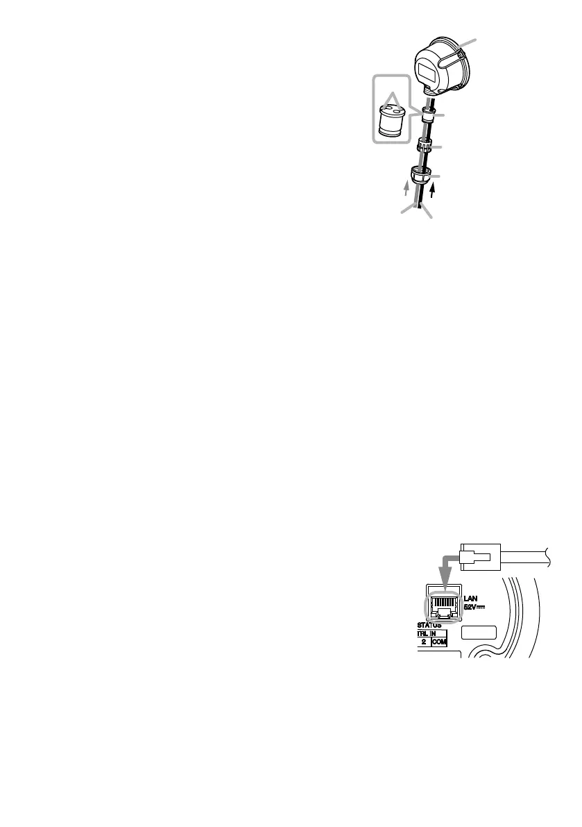
Step 3. Slide each part over the ends of the LAN cable
and control cable in the order shown in the gure
at right.
Tip
Feed the cable ends through the sealing bush
can be more easily done by pressing the cable
into the slots in the bush.
Step 4. Feed the ends of both the LAN cable and the
control cable through the recessed hole in the
rear cover to connect them to the LAN port and
terminals on the rear panel.
For connection method, see "Network Connection"
mentioned below and "Connections to Control
Input and Output Terminals" on the next page.
Step 5. Conrm that the ring gasket installed in the perimeter of the rear panel ts snugly in its
groove.
Step 6. Attach the rear cover to the speaker using the 3 rear cover screws.
Step 7. Slide the sealing bush and sealing clamp up the cable(s) and reinsert them into the recess
in the rear cover.
Step 8. Slide the sealing nut up the cable(s) and screw it securely into position.
After tightening the nut rmly by hand, secure it by rotating another 90° (1/4 rotation) using
a wrench.
Note
Take care not to overtighten the nut, as it could be damaged.
8. CONNECTIONS
8.1. NetworkConnection
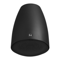
Connect the IP horn speaker to the PoE+ or PoE switching hub using
a LAN cable (straight UTP or STP cable, both rated at Category 5e
or greater and tted with RJ45 connectors). Power to the speaker is
supplied by the PoE+ or PoE switching hub.
Compatible switching hubs:
Switching hubs conforming to PoE+ (IEEE802.3at Class 4) or PoE
(IEEE802.3at Class 3) specications.
*Only when using the control functions
LAN cable
Sealing nut
Sealing clamp
Sealing bush
(accessory)
Slot
(Rear Panel)
From PoE+ (or PoE)
switching hub