9
7. INSTALLATION
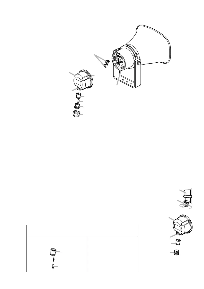
7.1. AttachingtheRearCover
[Beforeattachment]
Notes
• To ensure complete weatherproong, be sure that the following specications of cable are used for
both the LAN cable and the control input and output cable:
Cable diameter: ø4.5 to 5.2 mm or ø0.18" to 0.2"
Cable type: Round (not compatible with at or spiral type cables.)
• The recess is 14.3 mm or 0.56" in diameter. Use a LAN cable with an RJ45 plug that can pass
through this recess.
[Installationprocedure]
The rear cover is designed to meet specic weatherproong regulations (IP66 enclosure standards).
During installation, follow the below procedure to ensure that weatherproong performance is not
impaired.
Step 1. Turn the sealing nut counterclockwise to detach it from the rear cover.
Step 2. Remove both the sealing clamp and the sealing bush from the recess
in the cover.
Tip
Use the hole plug with the sealing bush as follows:
If using the control cable in
Step 3
If NOT using the control
cable in Step 3
Remove the plug from the
sealing bush.
Sealing bush
Hole plug
Leave the plug inserted
in the sealing bush.
* Attached to the rear cover when shipped
from the factory.
Rear cover
(accessory)
Sealing nut
Rear cover
(accessory)
Recess
Sealing clamp
Sealing bush
Removable terminal plugs
(3 pins)
Sealing clamp*
Hole plug*
Sealing bush*
Ring gasket
Screws
(3 places)
Recess