Section 2 – Operation
TOELLNER Electronic Instrumente GmbH
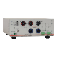
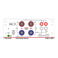
2.4.4 Connection of the consumer for switching the positive supply line
The consumer to be operated is connected to the OUT socket and the right-hand Minus
socket. Since the S1 switch carries the load current, the DIL switch S1 ENABLE must be in
the left position.
In the described switch configuration, the negative return line must always be connected
from the consumer to the voltage source via the minus sockets of the TOE 9261. These
minus sockets must never be bypassed, because otherwise some protection mechanisms
of the Electronic Switch are without effect, and damage to the Electronic Switch may
result.
2.4.5 Connection of the consumer for switching a ground line (minus)
The consumer to be operated is connected with the positive pole to the right-hand Plus
socket and the negative pole to the OUT socket. The latter is the switched ground point.
Since the load current is connected via the S2 switch in this configuration, this must be
activated using the DIL switch S2 + 0 Ω in position ON . The green LED next to the related
switch symbol is illuminated.
When switching a ground line (minus), the S2 + 0.1 Ω setting must never be selected,
otherwise the internal 0.1 Ω resistor would be overloaded during the flow of current.
The S1 switch parallel to the load can be deactivated by setting the DIL switch S1 ENABLE to
OFF . Otherwise the load would be discharged via S1 during the interruption. With
deactivation of the S1 switch also the above-mentioned improper load current flow via the
0.1 Ω resistor is automatically locked.
In the described switch configuration, the positive supply line from the voltage source to
the consumer must always be connected via the Plus sockets of the TOE 9261. These
plus sockets must never be bypassed, because otherwise some protection mechanisms of
the Electronic Switch are without effect, and damage to the Electronic Switch may result.
2.4.6 Connection of the control signal
A digital switching signal for controlling the power switch can be connected as desired to the
front panel or rear BNC CONTROL socket. A suitable clock source must be provided. This
signal should be compatible with one of the logic standards CMOS 5 V, LVCMOS 3.3 V or
TTL. Suitable devices include function generators in square wave or pulse mode as well as
arbitrary waveform generators (AWG) with digital waveforms. Voltages above 5 V as well as
negative voltages or voltages which extend into the negative range may not be used. Control
signals with a frequency up to 100 kHz can be used. An overload switch-off is carried out
above this frequency.
2.4.7 Control of switching paths and operation of the consumer
The digital switching signal is used to control the state of the paths S1 and S2. A conductive
path is thereby indicated by the red LED at the switch symbol S1 or S2 ( 2.4.8 Display of
the switching states). If the DIL switch CONTROL / INV is in the left position (i.e. no inversion),
S1 is conductive and S2 is non-conductive during a High level of the switching signal.
If however the DIL switch CONTROL / INV is set to INV , S1 is non-conductive and S2 is
conductive during a High level of the switching signal.