Section 2 – Operation
TOELLNER Electronic Instrumente GmbH
This results in the following possible operating conditions:
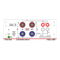
Configuration of TOE 9261
and consumer
Switching of positive supply line
Switching of return line (ground)
The appropriate setting of the CONTROL / INV DIL switch can therefore be selected
depending on the desired configuration (switching of positive supply line or of return line) and
the desired function of the control signal (High level should lead to supply of consumer or to
disconnection from the supply).
In the disconnected status of the consumer, a buffer stage present in the consumer and
possibly still charged is discharged if one of the two following cases exists:
TOE 9261 and consumer were connected in the configuration for switching the positive
supply line, and one of the two DIL switches S2 + 0.1 Ω and S2 + 0 Ω is set to ON
( 2.4.9 Use of the branch path).
TOE 9261 and consumer were connected in the configuration for switching the return line
(ground), and the DIL switch S1 ENABLE was not set to OFF .
If the CONTROL input is not connected or controlled but left in a high-impedance state,
this is evaluated as Low level. If in this case either the DIL switch CONTROL / INV is set to
INV or the DIL switch PULL-UP / ON to ON , the internally evaluated level changes to High,
resulting in switching path S1 becoming conductive and switching path S2 non-conductive.
In the configuration for switching the positive supply line, the consumer is then
permanently connected to the supplying voltage source.
In the configuration for switching the return line (ground), on the other hand, the consumer
is permanently connected to the supplying voltage source if – with the CONTROL input left
in a high-impedance state – the named DIL switches are either both in the left-hand or
both in the right-hand positions.
2.4.8 Display of the switching states
A conductive path S1 or S2 is indicated by the red LED at the related switch symbol. To
ensure always the perceptibility of the display, in case of high frequencies or short High or
Low pulses of the switching signal at the CONTROL input, not the actual fast changing
switching states are displayed, but it is calculated a slowed down signal for the display LEDs.
The switching paths themselves, however, are controlled by the timing of the switching
signal.
2.4.9 Use of the branch path
In the configuration for switching the positive supply line, S2 represents the load parallel
branch path. The switching state of the branch path S2 is always complementary to the state
of the longitudinal path S1. This means the consumer can be jumpered with S2, while S1 is
open (not conducting). This allows for example a buffer stage in the consumer to be
discharged.
To achieve the fastest possible discharging without a series resistor, DIL switch S2 + 0 Ω
must be set to ON . For indication the green LED next to the related switch symbol is
illuminated.