Section 2 – Operation
TOELLNER Electronic Instrumente GmbH
2.2 Description of the controls
At the end of the manual you will find the various operating and display elements for the
series TOE 9261 numbered with front panel and rear views. In the following the individual
operating elements are explained in detail.
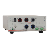
2.2.1 Front panel controls
Mains switch for turning the power to the device on and off. When the unit is ON the
green POWER LED will be illuminated.
8x DIL switch. Assignments from top to bottom (Nos. 1 to 8):
1. INPUT C: Apply input buffer capacitor to input socket pair Plus – Minus. Indication
by green LED.
2. R = 10 kΩ: Apply high-impedance base load 10 kΩ parallel to output socket pair
OUT – Minus. Indication by green LED.
3. R = 100 kΩ: Apply high-impedance base load 100 kΩ parallel to output socket
pair OUT – Minus. Indication by green LED.
4. S2 + 0.1 Ω: Apply branch path switch S2 with 0.1 Ω series resistor. Indication by
green LED ( 2.4.9 Use of the branch path).
5. S2 + 0 Ω: Apply branch path switch S2 without series resistor: Internal resistance
0 Ω. Indication by green LED ( 2.4.9 Use of the branch path).
6. S1 ENABLE: Activation / deactivation of switch S1 in order to carry out ground
interruptions using switch S2 ( 2.4.5 Connection of the consumer for switching a
ground line)
7. CONTROL: Inversion of the control signal present at front panel or rear
CONTROL input
8. PULL-UP: Apply pull-up resistor of approx. 22 kΩ to the front panel or rear
CONTROL input
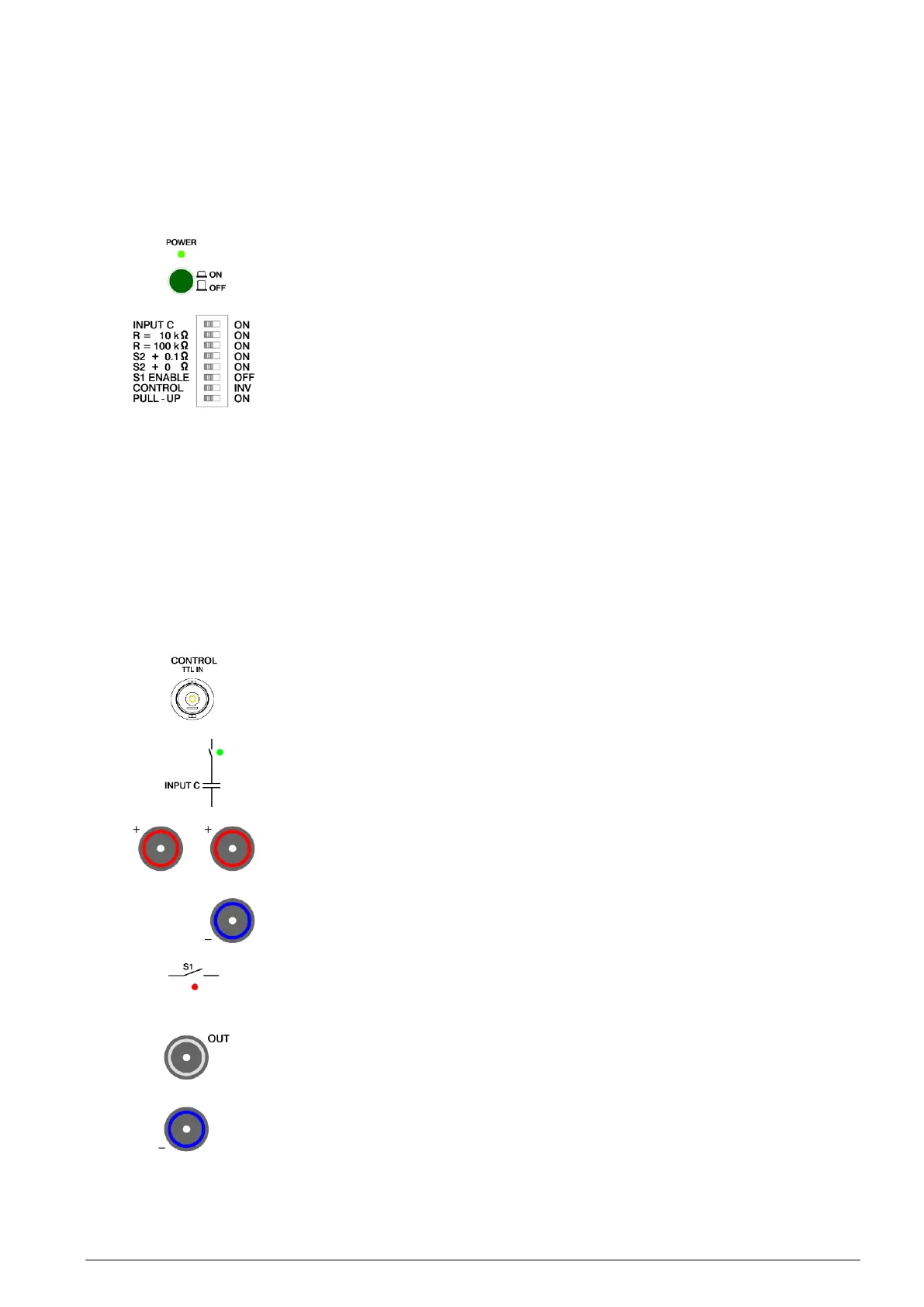
Front panel BNC input CONTROL for controlling the switching state both for the power
switch and the signal line switches ( 2.4.7 Control of switching paths and operation
of the consumer, 2.5.2 Control).
Selectable input buffer capacitor. This appears parallel to the input socket pair Plus –
Minus. The selection is indicated by the green LED next to the switch symbol.
Input sockets Plus – Minus of power switch. The input voltage should preferably be
connected to the right-hand Plus socket and to the Minus socket. The left-hand Plus
socket is used to connect the input voltage for carrying out ground interruptions.
An appropriate voltage source should be used to provide the input voltage. The
polarity and magnitude of the voltage must be observed; not more than the rated
voltage of the TOE 9261 may be applied.
Longitudinal path switch S1 of the power switch. Across this the connection between
the sockets Plus and OUT is applied. When S1 is conductive the red LED below the
switch symbol will be illuminated.
Output socket OUT and right-hand Minus socket of the power switch. In order to
switch the positive supply line of a consumer, this must be connected to OUT and to
the right-hand Minus socket. If, on the other hand, the return line of the consumer is to
be switched, the consumer must be connected with the positive pole to the right-hand
Plus socket [5] and the negative pole to OUT.
The voltage connected to OUT (in the case of a buffered and possibly preloaded
consumer) must not be more positive than the voltage at the Plus sockets or more
negative than the voltage at the Minus sockets.