Section 2 – Operation
TOELLNER Electronic Instrumente GmbH
2.2.2 Rear panel controls
The identifier shows the current version and the installed options for the unit.
This screw connects the housing to the protective earth.
Attention: This connection must never be removed!
Rear-side BNC input CONTROL for controlling the switching state both for the power
switch and the signal line switches ( 2.4.7 Control of switching paths and operation
of the consumer 2.5.2 Control).
The rating plate contains the following information: Company name, device series,
serial number, supply voltage with mains fuse and current draw.
Mains plug with
mains fuse
This 3-pole standardized plug is used with the mains power cord. Integrated into the
plug is the chamber for the device fuse with an additional compartment for a spare
fuse.
2.3 General operation features
Operation of the TOE 9261 for setting the desired switch and control configuration is carried
out using an 8-fold DIL switch on the front panel. The states of the selectable elements for
the load circuit as well as the switching states of the power switch are displayed by LEDs.
Switching time settings are made on the clock source used (e.g. function generator), which
may if desired be connected to the front or rear BNC input CONTROL on the TOE 9261.
2.4 Power switch operation
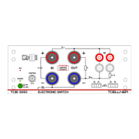
2.4.1 Connection of the input voltage source
To operate the power switch a DC voltage source (power supply, battery) is connected to the
input socket pair Plus – Minus. If the right-hand Plus socket is not used by the load for
carrying out ground interruptions ( 2.4.5 Connection of the consumer for switching a
ground line), the input voltage should be connected to this socket and to the Minus socket;
otherwise to the left-hand Plus socket and the Minus socket.
The applied voltage must be not greater than the rated voltage for the TOE 9261. Overlaying
with AC voltage is permissible as long as the input buffer capacitor is not applied and the
maximum momentary value of the total applied voltage does not exceed the rated voltage of
the TOE 9261 and the minimum momentary value is not negative. Setting a current limit at
the source with a value appropriate to the consumer or providing protection against
overcurrent is required.
It is imperative that the source be connected to the input sockets Plus – Minus with the
correct polarity! Otherwise damage to the Electronic Switch may result.
A current limiter or overcurrent fuse for the feed source is absolutely required.
2.4.2 Insertion of artificial networks
Depending on the requirement an impedance network, for example when operating or
testing motor vehicle components, an artificial network (AN) can be placed between the
voltage source and the input sockets or the output sockets and the consumer. In case of an
artificial network (AN) between voltage source and input sockets the input buffer capacitor
should not be applied, because otherwise the artificial network (AN) will be without effect.
2.4.3 Application of the internal input buffer capacitor
In all cases in which the internal input buffer capacitor can be used (DC input voltage without
overlaying with AC voltage, no artificial network between voltage source und input sockets),
this capacitor should be connected using the DIL switch INPUT C / ON . This results in an
improvement of the switching times, especially a shorter rise time. For indication the green
LED next to the related switch symbol is illuminated.