Section 2 – Operation
TOELLNER Electronic Instrumente GmbH
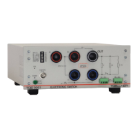
Selectable base load 10 kΩ or 100 kΩ. This appears parallel to the output socket pair
OUT – Minus. The selection is indicated by the green LED next to the switch symbol.
Branch path switch S2 of the power switch. This is used when switching the positive
supply line of a consumer to jumper the consumer during the switch-off time (switch
S1 of longitudinal path non-conductive) in order e.g. to discharge a buffer stage
present in the consumer. To this end, S2 is connected via the corresponding switching
function of the 8-fold DIL switch [2]. It is possible to select use of S2 without or with the
inserted 0.1 Ω series resistor ( 2.4.9 Use of the branch path). The 0.1 Ω series
resistor is used e.g. to implement the test signal in accordance with LV 124, version
2009, test E-10, test case 3.
If, on the other hand, the return line of a consumer is switched, S2 carries the load
current ( 2.4.5 Connection of the consumer for switching a ground line).
When S2 is conductive the red LED above the switch symbol will be illuminated.
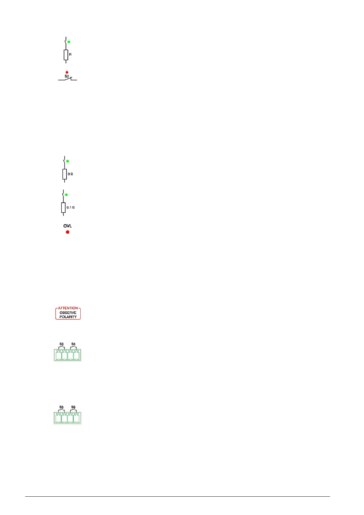
0 Ω series resistor for the branch path. When the branch path is selected in
conjunction with this resistor, the green LED next to the switch symbol will be
illuminated.
0.1 Ω series resistor for the branch path. When the branch path is selected in
conjunction with this resistor, the green LED next to the switch symbol will be
illuminated.
Red OVL LED (Overload). Comes on when a shutdown has occurred due to one of
the following fault conditions:
Max. switching frequency of 100 kHz on the control input has been exceeded
Overcurrent
Excessive temperature
A reset following a switching frequency fault is done by reducing the frequency at the
control input, or in case of overcurrent or excessive temperature by turning the unit off
and on using the mains switch. The reason for the overcurrent must be identified and
the cause removed. In case of excessive temperature the unit can be restarted only
after a sufficient cooling down time ( 2.6 Protection).
Polarity notice for the power switch. Voltages must be connected only with the correct
polarity. This means for the OUT socket that the connected voltage (in the case of a
buffered and possibly preloaded consumer) must not be more positive than the
voltage at the Plus sockets or more negative than the voltage at the Minus sockets.
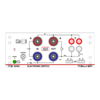
Terminal block for signal line switches S3 and S4. These can be used with suitable
terminal block plugs ( 4.1 Technical data TOE 9261, Connections, Signal line
switches).
The control and signal lines to be switched are routed through the signal line switches
indicated by the switch symbols S3 and S4. The connections for unused signal line
switches are left open.
The signal line switches are closed and opened synchronous with each other and
synchronous with closing and opening of the longitudinal path S1 of the power switch.
The terminal block for the signal line switches S5 and S6. The same explanations
apply as for S3 and S4 [14].