Section 2 – Operation
TOELLNER Electronic Instrumente GmbH
2.6 Protection
Series TOE 9261 devices use various protective devices which serve to prevent serious
damage to the units.
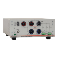
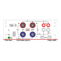
Make absolutely sure that the supplying voltage source is connected to the input sockets
Plus – Minus with the proper polarity!
Feedback from the (buffered) load side to the OUT output of the power switch must have
the indicated polarity and not exceed the rated voltage of the TOE 9261, i.e. the voltage
connected to OUT must not be more positive than the voltage at the Plus sockets or more
negative than the voltage at the Minus sockets! A voltage exceedance into the negative or
positive direction is only permissible after blocking S1 or S2 by means of inductance-
dependent, further flowing load current
Non-observance of these instructions may result in damage to the Electronic
Switch.
2.6.1 Overcurrent and short-circuit protection of the switching paths
The overcurrent and short-circuit protection of the switching paths is designed to guard the
TOE 9261 against overload from excessive currents. It extends through the longitudinal and
branch paths of the power switch as well as through the signal line switches.
When the overcurrent and short-circuit protection is triggered, the internal driver stages are
permanently turned off, i.e. the switching paths are no longer driven.
This fault status is indicated by the OVL LED.
A reset is accomplished by turning the unit off and on using the mains switch. The cause of
the overcurrent or short-circuit must be identified and eliminated.
2.6.2 Input overcurrent protection
The input overcurrent protection guards the power switch against excessively high periodic
supply of power which results from the inductance on the input cable at the moment the
longitudinal path is turned off.
When the input overcurrent protection is triggered, the internal driver stages are permanently
turned off, i.e. the switching paths are no longer driven.
A fault condition is indicated by the OVL LED.
Reset by turning the unit off and on using the mains switch.
The following measures can be taken to prevent too high periodic supply of inductive energy
and thereby an undesired triggering of the input overcurrent protection:
Minimize the cable length to the input sockets Plus – Minus
Parallel, closely adjacent routing of both cable conductors
Use of a feed source with high output buffer capacity
Apply the built-in input buffer capacitor
2.6.3 Protection against exceeding of the maximum switching frequency
To protect against excessive switching losses and against excessive driver output, the
maximum switching frequency is limited.
Applying a higher frequency at the CONTROL input results in shutting off of the internal
driver stages, i.e. the switching paths are no longer driven.
This fault condition is indicated by the OVL LED.
The fault condition remains as long as the non-permitted switching frequency is present. If
the frequency is first reduced significantly below the permissible limit (taking into account a