BAG G Mold F-01-1 Left Castor Block - 4 x 1
Mold F-02-1 Right Castor Block - 4 x 1
4152-P4S1-1 Castor Block Insert x 4
PA-HBS003-1 5.3mm Ball (Steel) x 4
PA-SS0312BK-1 M3x12mm Set Screw x 2
PA-SS0308BK-1 M3x8mm Set Screw x 2
PA-CM0310BK-1 M3x10mm Countersunk Screw x 2
Page 14
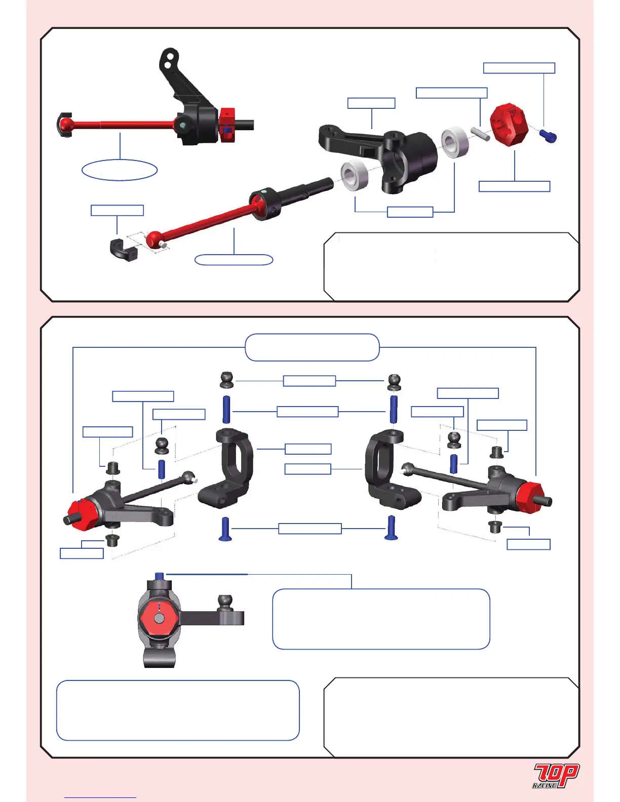
STEERING BLOCK ASSEMBLY (cont’d)
STEP 17
STEP 16B (Make 2 for Foam Carpet Edition ONLY)
BAG G Mold G-01-1 Steering Block x 2
PO-DT1004RD-A-1 5.2mm Wheel Hub x 2
PO-DT1004RD-B-1 2 x 10mm Wheel Hub Pin x 2
PO-DT1004RD-C-1 M2 Wheel Hub Screw x 2
MR105ZZ-1 5 x 10 x 4mm Bearing x 4
PO-DT0006-1 Dog Bone C Drive x 2
STEP 16B
FINISHED
from STEP 14A
PO-DT1004RD-A-1
MR105ZZ-1
PO-DT1004RD-B-1
PO-DT1004RD-C-1
Mold G-01-1
PO-DT0006-1
Rubber Edition: from STEP 16A
Foam Edition: from STEP 16B
Mold F-01-1
Mold F-02-1
PA-CM0310BK-1
PA-SS0312BK-1
PA-HBS003-1
PA-HBS003-1
PA-HBS003-1
PA-SS0308BK-1
PA-SS0308BK-1
4152-P4S1-1
4152-P4S1-1
4152-P4S1
4152-P4S1
Note: The same steps apply for both rubber and
foam edition. The only difference is the part from STEP
16. The diagram only shows the assembly from STEP
16A for the rubber edition; for foam addition, use the
assembly from STEP 16B instead.
Note: For each steering block assembly,
make sure the set screw thread is exposed by
2.5 to 3.0mm and be sure not to overtighten it
because this would cause the end of the screw to
touch the universal axle.
 Loading...