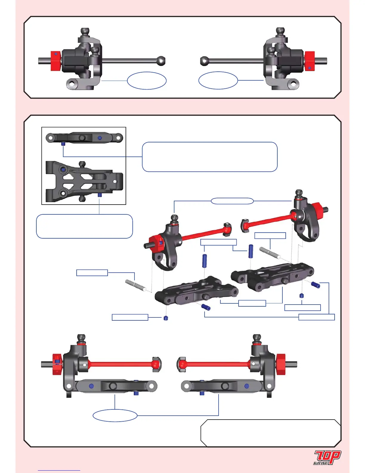
BAG H Mold E-02-1 Rear Suspension Arm x 2
TC-PSU001-1 3mm x 23mm Hinge Pin x 2
PA-SS0306BK-1 M3x6mm Set Screw x 2
PA-SS0308BK-1 M3x8mm Set Screw x 4
Page 15
STEERING BLOCK ASSEMBLY (cont’d)
STEP 18
STEP 17 (cont’d)
REAR SUSPENSION ASSEMBLY
STEP 18
FINISHED
Mold E-02-1
from STEP 15
PA-SS0308BK-1
TC-PSU001-1
TC-PSU001-1
PA-SS0308BK-1
PA-SS0306BK-1
PA-SS0306BK-1
Note: Downstop (droop) level should be adjusted
based on your personal setup preference or according
to the setup sheets on Page 29 for Rubber Asphalt
Edition or Page 30 for Foam Carpet Edition.
Note: For each pivot ball
location make sure the set screw
thread is exposed by 2.5 to 3.0mm.
STEP 17
(Left Side)
FINISHED
STEP 17
(Right Side)
FINISHED