Page 16
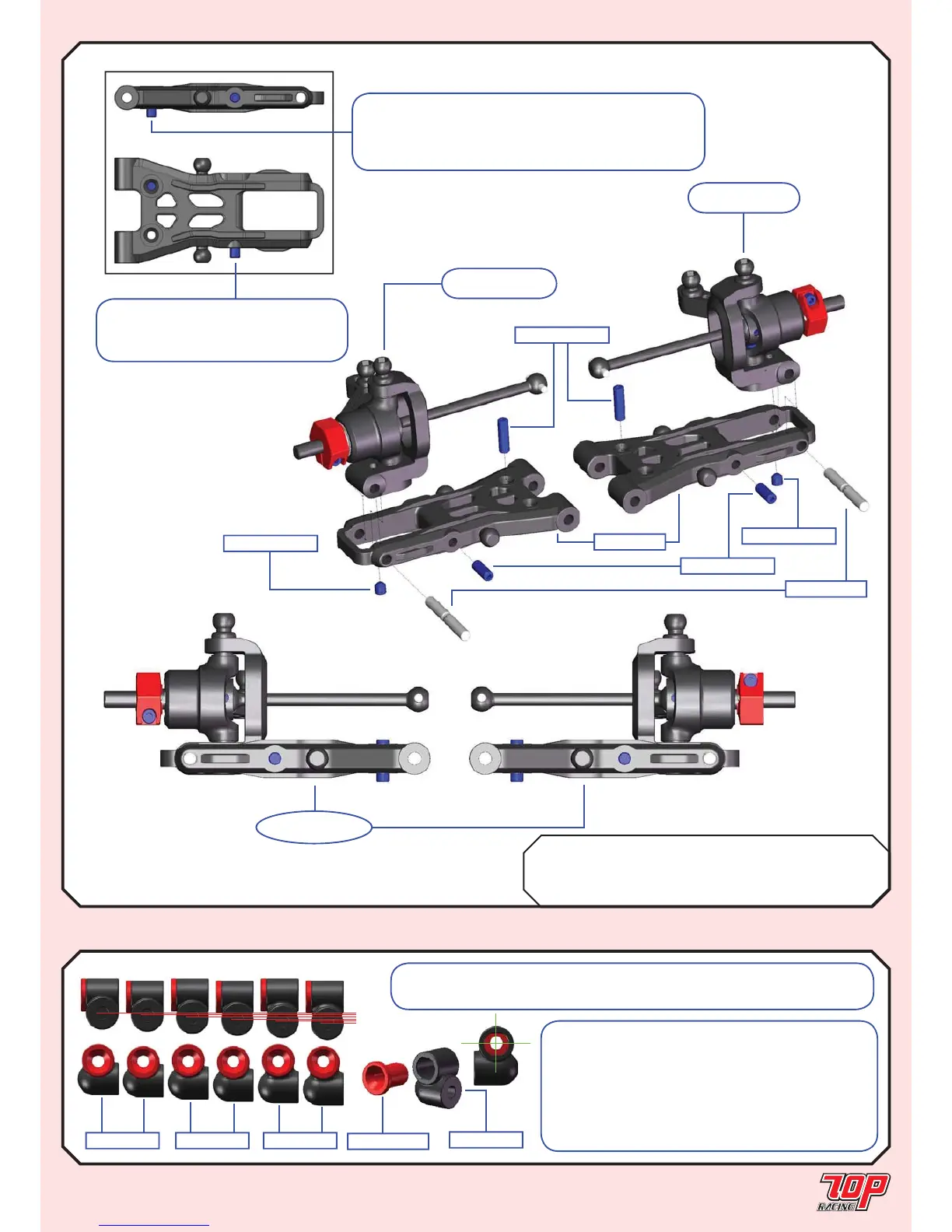
STEP 19
FINISHED
FRONT SUSPENSION ASSEMBLY
STEP 19
BAG H Mold E-01-1 Front Suspension Arm x 2
TC-PSU001-1 3mm x 23mm Hinge Pin x 2
PA-SS0306BK-1 M3x6mm Set Screw x 2
PA-SS0308BK-1 M3x8mm Set Screw x 4
from STEP 17
(LEFT SIDE)
TC-PSU001-1
PA-SS0308BK-1
from STEP 17
(RIGHT SIDE)
PA-SS0308BK-1
Mold E-01-1
PA-SS0306BK-1
PA-SS0306BK-1
Note: The alloy suspension mount insert is
off-centered. To rotate the insert up side down
would lower or heighten the suspension mount
by 0.5mm. In combination with the 3 plastic
suspension mounts with increment of 1.0mm,
it would give you 6 steps of suspension mount
height adjustments with 0.5mm increments.
Note: Pay attention to the orientation of the suspension mount inserts
based on your setup. The screw hole is vertically offset by 0.25mm.
SUSPENSION MOUNT
STEP 20
Mold M-02-1
TC-PSU007-1
Mold M-02-1Mold M-01-1 Mold M-03-1
H
H
M
M
L
L
Note: For each pivot ball
location make sure the set screw
thread is exposed by 2.5 to 3.0mm.
Note: Downstop (droop) level should be adjusted
based on your personal setup preference or according
to the setup sheets on Page 29 for Rubber Asphalt
Edition or Page 30 for Foam Carpet Edition.