Rubber Foam
BAG H
*SUSMF
Mold M-02-1 Suspension Mount B - MRC x 4
Mold M-02-1 Suspension Mount B - MRC x 4
TC-PSU007-1 Suspension Mount Insert x 4 x 4
TC-PSU002-1 3mm x 51mm Hinge Pin x 2 x 2
*SUS1/1
AW-M100RD-1 Large 3mm Spacer (t = 1.0mm)
x 2
AW-M080SV-1 Large 3mm Spacer (t = 0.8mm) x 2
*SUS2/1 AW-M100RD-1 Large 3mm Spacer (t = 1.0mm) x 2
*ARM1
AW-S150RD-1 3 x 5.5 x 1.5mm Collar x 2
AW-S150RD-1 3 x 5.5 x 1.5mm Collar x 2
*ARM2
AW-S150RD-1 3 x 5.5 x 1.5mm Collar x 2
AW-S150RD-1 3 x 5.5 x 1.5mm Collar x 2
PA-CM0314BK-1 M3x14mm Countersunk Screw x 4 x 4
PA-CM0316BK-1 M3x16mm Countersunk Screw
Page 18
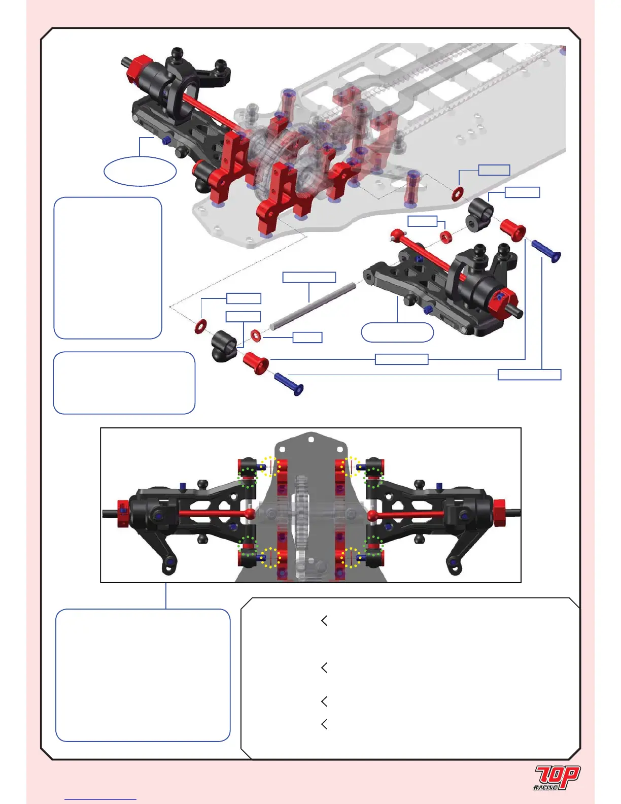
FRONT SUSPENSION
STEP 22
Note:
1. The thicknesses and positions of
the large spacers determines tread
width and toe angle (marked by “yellow
dots”).
2. The thicknesses and positions of
the small spacers determine the wheel
base in the foward/rearward direction
(marked by “green dots”).
*Refer to the setup sheet for more
details.
PA-CM0314BK-1
TC-PSU002-1
*ARM1
*ARM2
TC-PSU007-1
*SUSMF
*SUSMF
*SUS1/1
from STEP 19
Left Side
STEP 22
(RIGHT SIDE)
FINISHED
SUS2/1
Note: The fi gure shows
the assembly of the left-front
suspension. Assemble the
right-front suspension in a
symmetrical manner.
Note: Pay special
attention to the
orientation of TC-
PSU007 according
to the standard setup
sheet for rubber asphalt
and foam carpet
edition. Refer to page
15 to understand how
the orientation affects
suspension mount
height.
 Loading...