BAG I Mold H-02-1 Ball Cup - 14.5mm x 10
Mold H-03-1 Ball Cup - 18.5mm x 4
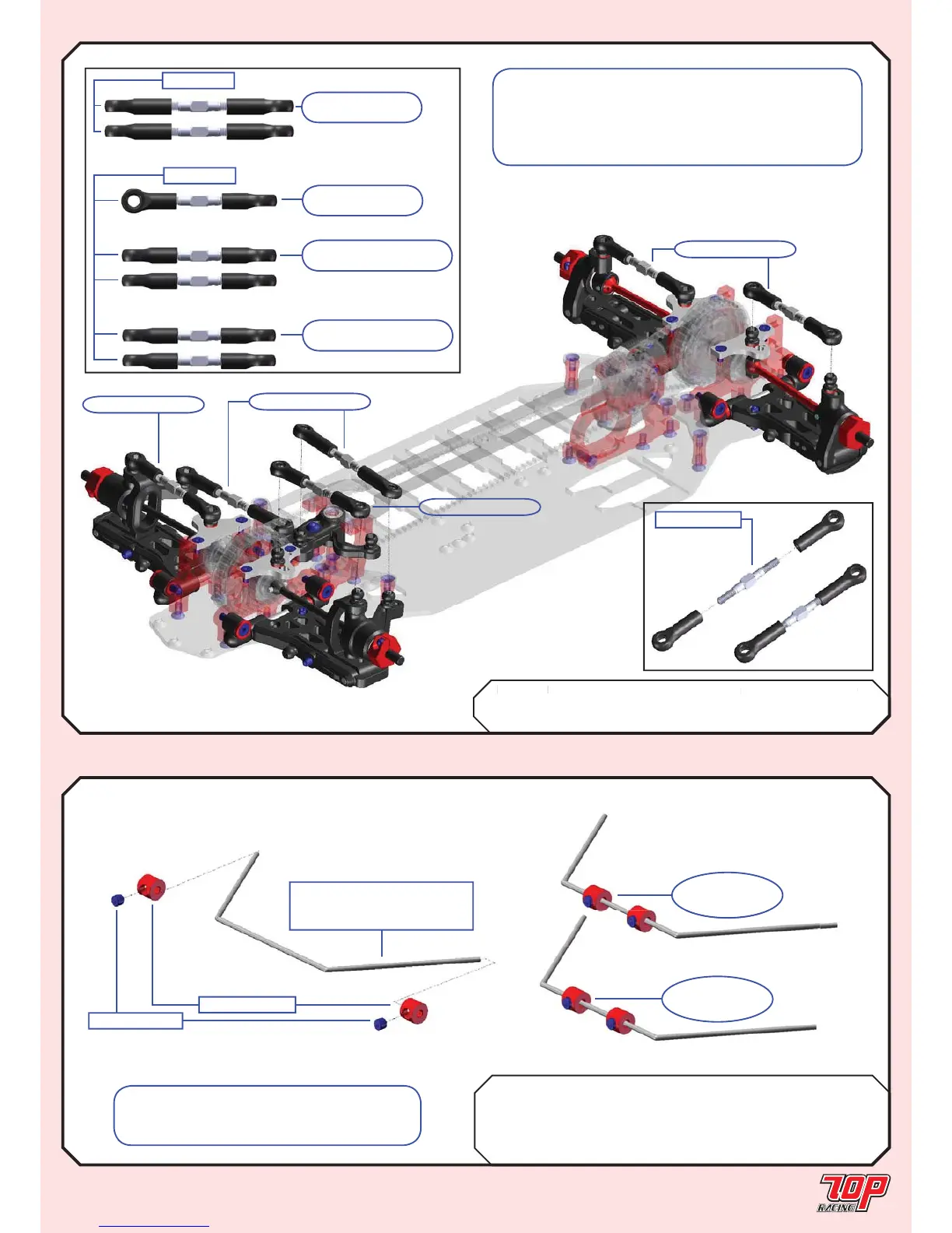
TC-PSU005-1 3mm x 30mm Tie Rod (Steel) x 7
Page 19
LINKAGE
STEP 23
Rubber Foam
BAG I TC-PSB012-1 1.2mm Stabilizer Bar x 2
TC-PSB014-1 1.4mm Stabilizer Bar x 1
AW-ST01RD-A-1 Aluminum Stopper (Red) x 4 x 2
PA-SS0303BK-1 M3x3mm Set Screw x 4 x 2
STABILIZER BAR
from STEP 23A
from STEP 23C
from STEP 23D
from STEP 23C
STEP 24
TC-PSU005-1*
STEP 23A
Steering Tie Rod
STEP 23C
Front Camber Tie Rod
STEP 23D
Rear Camber Tie Rod
STEP 23B
Servo Tie Rod
Mold H-02-1
Mold H-03-1
PA-SS0303BK-1
Rubber Edition: TC-PSB012-1
Foam Edition: TC-PSB014-1
AW-ST01RD-A-1
STEP 24
(Rubber)
FINISHED
STEP 24
(Foam)
FINISHED
Note: Make 2 sets of stabilizer bar
assembly (1.2mm) for rubber version and 1
set of (1.4mm) for foam version.
Note: Tie Rod lengths are not shown in scale.
Please adjust length according to the standard setups
on page 27 for STEP 23B(servo tie rod adjustment)
and page 29-30 for STEP 23A, C and D (camber and
toe angle adjustments).