Installation
Installing Diversity Antenna
2-15
P/N: 1049060-01
Installing Diversity Antenna
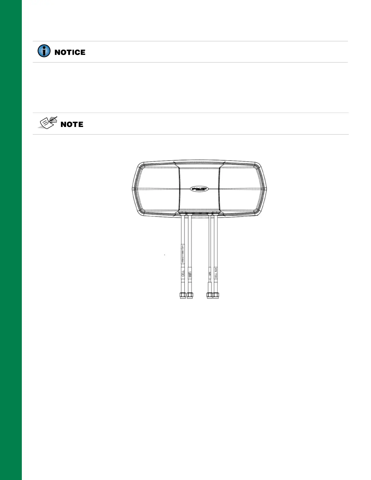
The Diversity Antenna (P/N 1031211-01) includes a magnetic base (Figure 2-19).
1. To install the antenna, simply place it in a clear open space on the roof of the cab.
2. Route the antenna leads down to connect into the MC-X3 controller (Figure 2-20 on page 2-16).
Figure 2-19: Diversity Antenna
Installing Radio Antenna
The Radio Antenna Assembly (P/N 1043614-01) shown in Figure 2-20 on page 2-16, is a magnet
mount antenna base.
There are two optional antenna elements:
• P/N 9900-1068, PDL Antenna 2.4DBI, 450-470MHZ
• P/N 30-030014-01, Antenna, 896-970MHZ Modem
1. Screw the appropriate antenna element into the magnet mount base.
2. Place the magnet mount assembly with antenna on the cab roof. Keep as much distance as
possible between the radio antenna, Diversity Antenna, and the GNSS receivers.
Antennas must be mounted as far away as possible from the GNSS receivers and
other antennas.
Each lead is labeled and the connections are unique.