Product Description
P/N: 1049060-01
1-1
Introduction
Product Description
3D-MC
MAX
integrated 3D machine control system together with the MC-X3 controller combines TS-i4
IMU sensors, GNSS receivers, and a GX-55 touchscreen display for the Topcon dozer grade control
system. This manual covers the installation procedure for the 3D-MC
MAX
integrated 3D machine control
system with MC-X3 control for the Caterpillar D5 and D6 dozers (Figure 1-1).
Preparing for Installation
Following the processes and recommendations in this section will help ensure that your installation
goes smoothly and minimizes the amount of time a machine is away from the work site.
Required Hardware
Open the hardware boxes and use the packing lists to confirm that all system items are present and
undamaged.
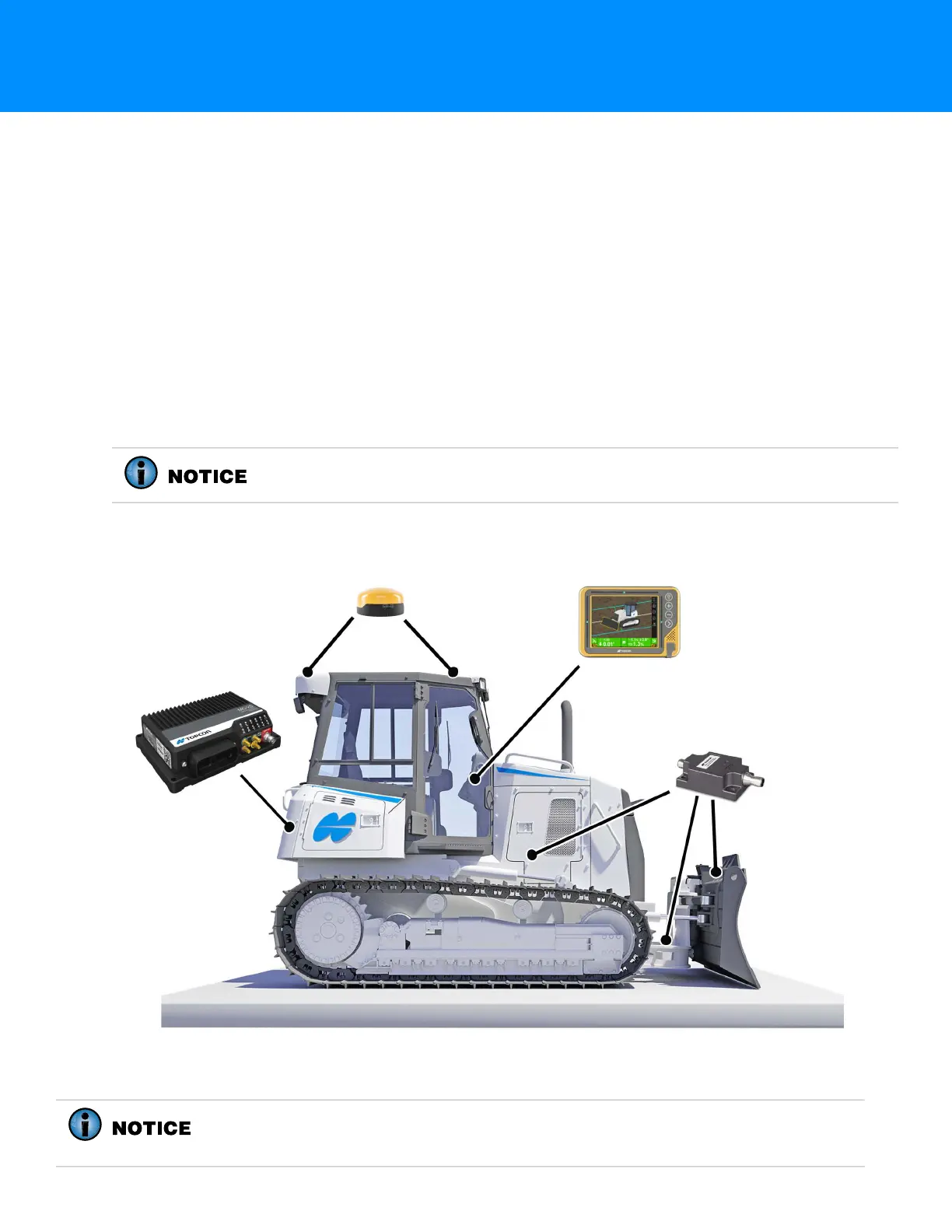
Figure 1-1: Major Hardware Parts—Dozer
HW KIT, DZR CR D5/D6 MAX X3 i3, P/N 1041569-01, is required for this
installation.
GR-i3/GR-i3F
Receivers (2 PLCS)
GX-55 Touchscreen
Display
TS-i4 IMU Sensors
(3 PLCS - Body, C-Frame, Blade)
MC-X3 Controller
HW KIT, DZR CR D5/D6 MAX X3 i3, P/N 1041569-01, also includes hydraulic hose
and weld-on hose clamps. These should be cut to fit and used as needed to
protect cables, particularly for the blade, C-Frame, and body TS-i4 sensors.