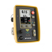
GC-35 Setup
Control Screen
3
P/N: 1001548-01
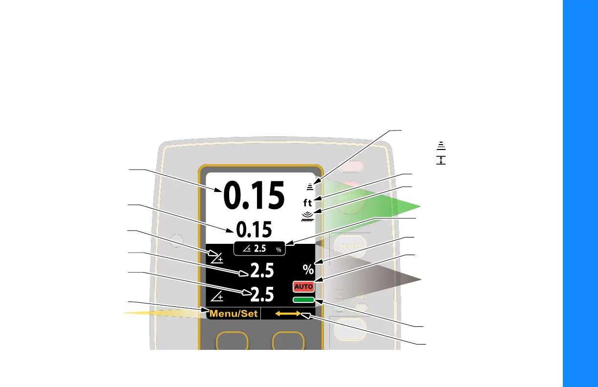
Control Screen
The Control Screen displays when you power on the control box. It is your interface with the components of your
Topcon System. The Control Screen changes depending on how you have configured your Control Box and your
Topcon System.
The illustration below shows an example of a Control Box set up to display information from a secondary Control Box
set up for Slope Control.
Elevation Set
Point Value
Actual Elevation
Sensor Reading
Slope Set Point Value
Positive/Negative
Slope Indicator Icon
Actual Slope
Sensor Reading
Menu/Set
Button Function
Display Area
Elevation Icon
Paver:
Proler:
Units (ft/in/cm)
ST-3 Surface/Stringline Mode Icon
Display Slope Box
Auto Icon
Slope Icon
Primary Control Box Display Area
Secondary Control Box
Display Area
Cross Communication
On-Grade Icon
GC-35_QRG.book Page 3 Tuesday, January 31, 2017 3:43 PM