24
(#21).
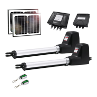
2. Battery OR AC-DC power supply (Required but not included)
Please connect them following the chapter of ―Connection of the power supply‖.
3. Adapter (Only used to charge the batteries)
Insert the stripped cable wires into ADAPTER (#13) terminals to the control board. No matter the polarity.
4. Warning Light (Included in some models, refers to the actual package)
The red wire of the warning light should be inserted into +LAMP (#15) terminal, the white wire into the LAMP-
(#16).
5. Photocell Beam System (PBS) (Included in some models, refers to the actual package)
Use a 2-core cable to connect the ―+ ~‖ terminal of the photocell’s emitter to the “+24”(#1) terminal, the ―- ~‖
terminal to the “GND”(#3) terminal. Also the ―+ ~‖ and ―- ~‖ terminals of the photocell’s receiver should be
connected to the “+24” and “GND” terminals in parallel.
Use another 2-core cable to connect the ―NC‖ terminal of the receiver to the “PHOTO”(#2) terminal, the ―COM‖
terminal to the “GND”(#3) terminal.
6. Push Button (optional)
The push button should be wired to the “#4 and “#5” terminals. No matter the polarity. The gate operator works
alternately by pressing the button (open-stop-close-stop-open).
7. Electric Lock (optional)
A lock plus board is required to connect the electric lock to the control board. The 2 wires of J1 of lock plus
should be wired to the “9#” and “10#” terminal of the control board. No matter the polarity. Red wire of J2 should
be wired to the 11# terminal and yellow wire of J2 should be wired to the 12# terminal of the control board. Red
wire of J3 should be connected to the red wire of electric lock and also the yellow wire of J3 should be
connected to the yellow wire of electric lock.
8. Exit Wand (optional)
The BLACK wire of the exit wand should be connected into the “#5” terminal.
The BLUE wire of the exit wand should be connected into the “#6” terminal.
The RED wire of the exit wand should be connected into the “#11” terminal.
The GREEN wire of the exit wand should be connected into the “#12” terminal.
The sensitivity adjustment board should be wired to the GREEN wire and the YELLOW wire of the wand. No
matter the polarity.
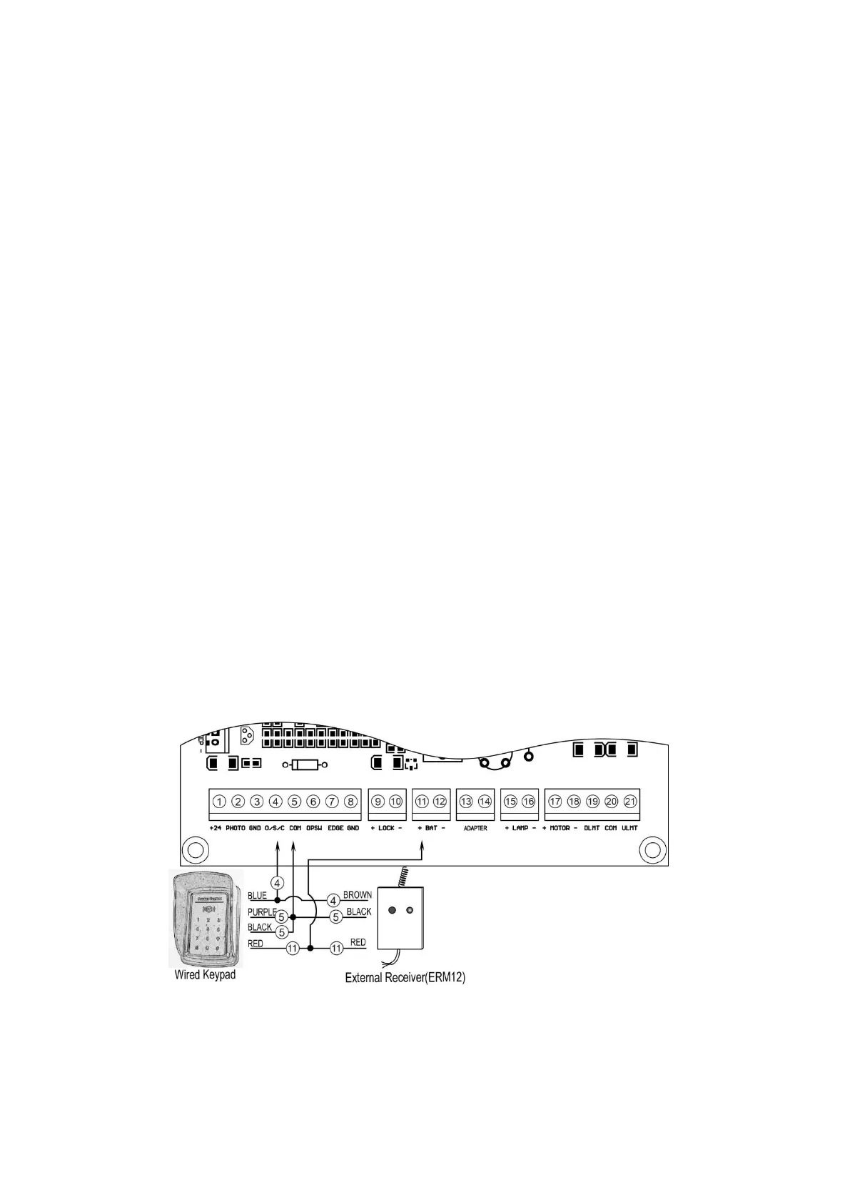
9. Wired Keypad (24VDC) (optional)
The RED wire of the wired keypad should be connected into the “#11” terminal.
The BLACK wire of the wired keypad should be connected into the “#5” terminal.
The PURPLE wire of the wired keypad should be connected into the “#5” terminal.
The BLUE wire of the wired keypad should be connected into the “#4” terminal.
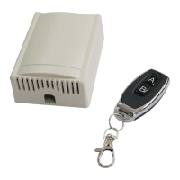
10. External receiver (optional)
The RED wire of the external receiver should be connected into the “#11” terminal.