D
Deborah JohnsonJul 27, 2025
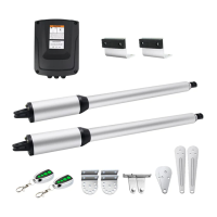
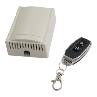
Why Topens CK1200 Gate Opener remote control does not work?
- CCynthia MillerJul 27, 2025
If the indicator light on the remote isn't lighting up, the battery may be dead and needs replacing. Ensure you are within range of the opener. If the remote still isn't working, it may not be properly paired with the receiver. Try erasing the remote control codes and re-programming them. If the issue persists, the control board may need to be checked or replaced.