24 2 - Operation and maintenance
TO320 M - EN - Ed. 04.09
Motor-operated VDC12.5
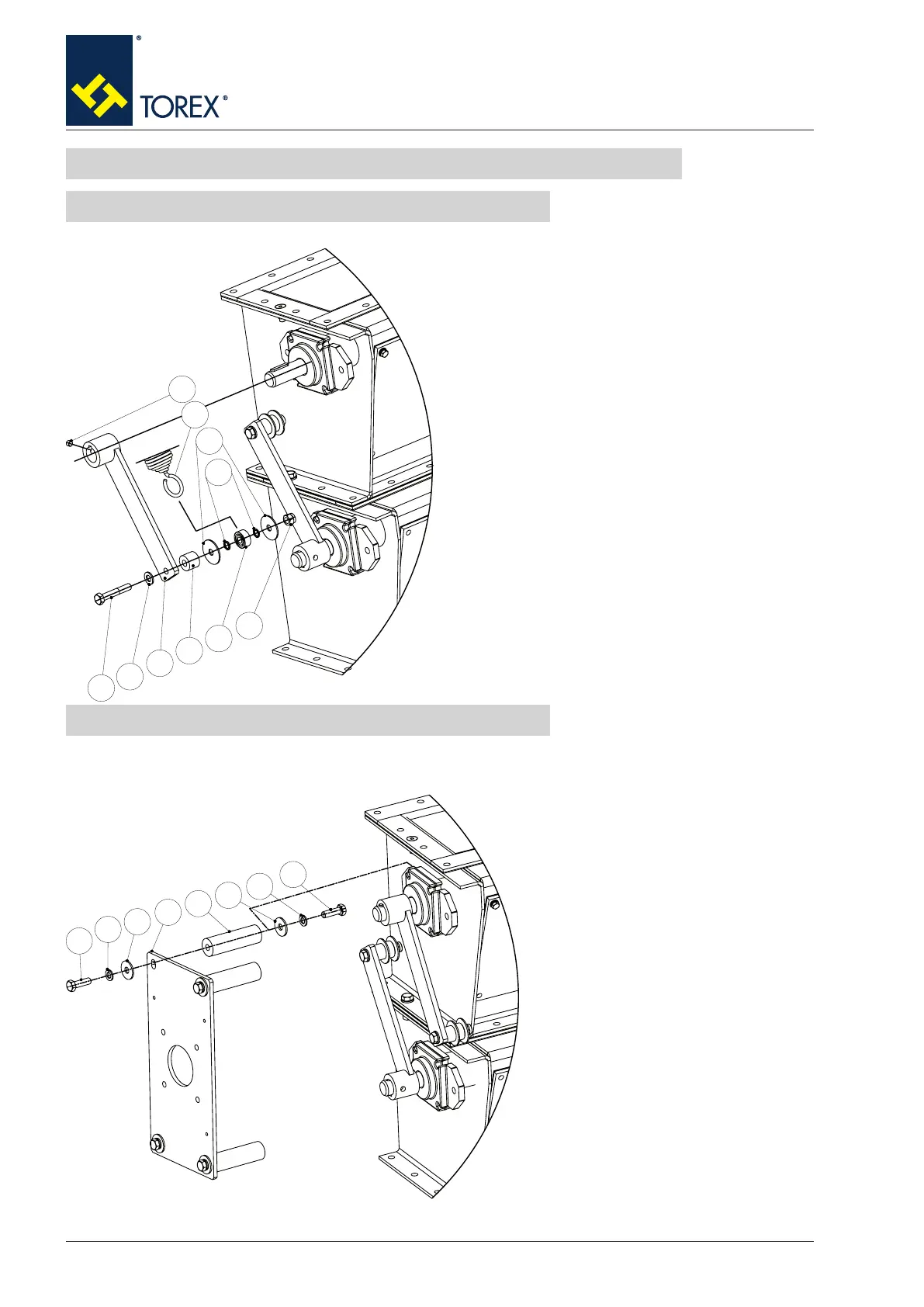
Levers assembly order12.5.1
1. Fit lever (1) on the shaft of the VDC ensuring
that the key present on the shaft is centred in
relation to the lever;
2. Fit grub screw (10) on the lever;
3. Insert screw (9) and washer (8) in lever (1);
4. Insert spacer (2), a washer (6), a spacer (5)
and bearing (3) on screw (9);
NOTE: repeat these operations for the other le-
ver.
5.Insert spring (7) on bearing (3);
6.Insert spacer (5) and washer (6);
7. Screw nut (4).
NOTE:
repeat these operations for the other lever.
Drive unit support assembly order12.5.2
1. Position the stud bolts (19) on the
valve body and t screws (16) (RH
screw in drawing) together with
washers (17-18);
2. Position the drive unit support
plate (20) on stud bolts (19) and t
screws (16) (LH screw in drawing)
together with washers (17-18).
4
6
5
3
2
1
8
9
10
7
17
18
19
20
18
17
16
16


 To Next Page