4.Locatetheopenconnectoronthemainwire
harnesstotherightoftheseatandconnectitto
thewireharnessthatcamewiththeseat.
5.Routetheseatwireharnessaroundtheseat
slides,ensuringthatitisnotpinchedwhenyou
movetheseat,andconnectittotheportonthe
bottomoftheseat.
3
InstallingtheSteering
Wheel
Partsneededforthisprocedure:
1
Steeringwheel
1
Locknut(1-1/2inches)
1Washer
1
Steering-wheelcap
Procedure
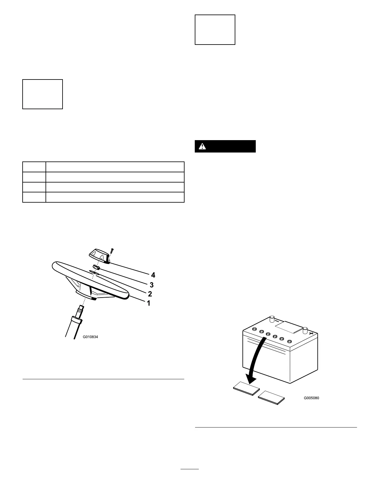
1.Slidethesteeringwheelontothesteeringshaft
(Figure5).
g010834
Figure5
1.Steeringwheel
3.Locknut
2.Washer
4.Cap
2.Slidethewasherontothesteeringshaft(Figure
5).
3.Securethesteeringwheeltotheshaftwitha
locknutandtightenitto27to35N∙m(20to26
ft-lb)(Figure5).
4.Installthecaptothesteeringwheelandsecure
itwith6bolts(Figure5).
4
ActivatingandCharging
theBattery
NoPartsRequired
Procedure
Useonlyelectrolyte(1.265specicgravity)tollthe
batteryinitially.
WARNING
Batteryterminalsormetaltoolscouldshort
againstmetalmachinecomponents,causing
sparks.Sparkscancausethebatterygasses
toexplode,resultinginpersonalinjury.
•Whenremovingorinstallingthebattery,
donotallowthebatteryterminalstotouch
anymetalpartsofthemachine.
•Donotallowmetaltoolstoshortbetween
thebatteryterminalsandmetalpartsofthe
machine.
1.Removethefastenersandbatteryclampand
liftoutthebattery.
Important:Donotaddelectrolytewhilethe
batteryisinthemachine.Youcouldspillit,
causingcorrosion.
2.Cleanthetopofthebatteryandremovethevent
caps(Figure6).
g005080
Figure6
3.Carefullylleachcellwithelectrolyteuntilthe
platesarecoveredwithabout6mm(1/4inch)
ofuid(Figure7).
12