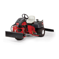
Theimplement/chargepump(P2)isaxeddisplacementgerotorpumpthatis
partofthetractionpump.Theimplement/chargepumpalsosuppliesuidow
fortheliftcircuitandthechargecircuitoftheclosedlooptractionsystemforboth
model08743and08745machines.Theimplement/chargepumpalsosupplies
uidowtothesteeringcircuitonmodel08745machines.Onmodel08745
machines,thepumpoutputowstothesteeringcontrolvalvebeforesupplying
theliftandchargecircuitneedssothatthesteeringcircuithaspriority.
Onmodel08743machines,thesteeringandliftcircuitpressureislimitedto
5,171kPa(750psi)byareliefvalveinaremotemanifoldlocatednearthelift
valve.Onmodel08745machines,thesteeringandliftcircuitpressureislimited
to5,171kPa(750psi)byareliefvalvelocatedinthesteeringvalve.
Theliftvalvehas4separateoperatingpositions:NEUTRAL,RAISE,LOWER,and
FLOAT.Thestandardrearliftvalveandtheoptionalfrontliftvalveoperatethe
same.
LiftValveintheNeutralPosition
WhentheliftleverisintheNEUTRALposition,theliftsystemisnotactively
raising,loweringoroating.Hydraulicuidowfromtheimplement/charge
pumpbypassestheliftcylinderthroughtheliftvalveintheNEUTRALposition.
TheHydraulicuidreturnstothetankasanormalpartofthecharge,casedrain,
andbleedoffcircuits.
LiftValveintheRaisePosition
MovingtheliftlevertotheRAISEpositionallowstheliftcontrolvalvetodirectuid
owfromtheimplement/chargepumptotherodendoftheliftcylinder.The
pistonmovesintothecylinderpushinguidfromthecapendofthecylinderand
tothetank.Asthecylinderrodretracts,theattachmentisraised.Whenthe
cylinderreachestheendofitsstroke,oriftheliftmechanismispreventedfrom
raising,thereliefvalveinthesteeringvalveopensanddirectsthehydraulic
owoutthesteeringvalveTporttotheoilcooleruntiltheliftleverisreleased.
Whentheliftleverisreleased,theliftvalvereturnstotheneutralposition.The
attachmentisheldinpositionbycheckvalvesintheliftvalve.
LiftValveintheLowerPosition
MovingtheliftlevertotheLOWERpositionallowstheliftcontrolvalvetodirect
uidowfromtheimplement/chargepumptothecapendoftheliftcylinder.The
pistonmovesoutofthecylinderpushinguidfromtherodendofthecylinderand
tothetank.Asthecylinderrodextends,theattachmentislowered.Whenthe
cylinderreachestheendofitsstroke,oriftheliftmechanismispreventedfrom
lowering,thereliefvalveinthesteeringvalveopensanddirectsthehydraulic
owoutthesteeringvalveTporttotheoilcooleruntiltheliftleverisreleased.
Whentheliftleverisreleased,theliftvalvereturnstotheneutralposition.The
attachmentisheldinpositionbycheckvalvesintheliftvalve.
LiftValveintheFloatPosition
Asanattachmentmovesoverterrainwithchangingelevation,theliftmechanism
shouldbeallowedtomoveupanddown(oat)tofollowgroundcontoursduring
operation.Aftertheattachmentisfullylowered,andtheliftleverismovedtothe
FLOATposition,apathisopenintheliftvalveforuidatbothendsofthelift
cylindertoowineitherdirectionifnecessary.Anadjustabledetentplateallows
theliftlevertobeheldintheoatposition;refertothetractionunitOperator’s
Manualtoadjusttheliftleverdetentplate.
HydraulicSystem:HydraulicFlowDiagrams
Page5–20
SandPro
®
3040and5040
20251SLRevA

 Loading...