insidethewheels,thenllthisareaoneachsideof
eachwheelwithgrease.
11.Installthelargewashersonthewheelsoverthe
grease.
12.Installtheinnertensionwheelandsecureitwiththe
nutremovedpreviously(Figure43).
13.Torquethenutto300ft-lb(407N-m).
14.Installthenewtrack,ensuringthatthelugsinthe
tracktbetweenthecogsinthemiddleofthedrive
sprocket(Figure43).
15.Installtheoutertensionwheelandsecureitwiththe
nutremovedpreviously(Figure43).
16.Torquethenutto300ft-lb(407N-m).
17.Turnthetensioningscrewcounter-clockwiseuntil
thedistancebetweenthetensionnutandthebackof
thetensiontube(Figure40)is2-3/4inches(7cm).
18.Aligntheclosestnotchinthetensionscrewtothe
lockingboltholeandsecurethescrewwiththe
lockingboltandnut.
19.Repeatsteps2through18toreplacetheothertrack.
20.Lowerthetractionunittotheground.
MaintainingtheRoadWheels
1.Removethetracks;refertoReplacingtheTracks.
2.Removethe4boltssecuringeachlowertrackguide
whichcontainstheroadwheels,andremovethem
(Figure44).
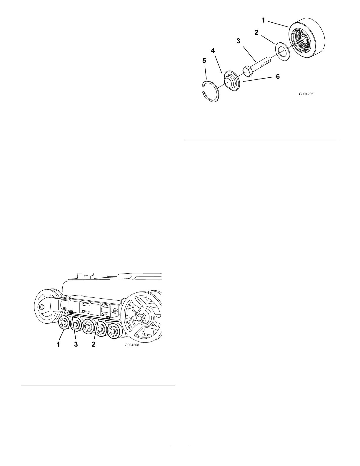
Figure44
1.Roadwheels
3.Trackguidebolts(onlytwo
shown)
2.Lowertrackguide
3.Removethesnapringandcapfromaroadwheel
(Figure45).
Figure45
1.Roadwheel4.Roadwheelcap
2.Gasket5.Snapring
3.Bolt6.Addgreaseunderthecap
4.Checkthegreaseunderthecapandaroundthe
gasket(Figure45).Ifitisdirty,gritty,ordepleted,
cleanoutallofthegrease,replacethegasket,and
addnewgrease.
5.Ensurethattheroadwheelturnssmoothlyonthe
bearing.Ifitisfrozen,replacetheroadwheelas
describedintheRoadWheelKitInstallationInstructions
orcontactyourAuthorizedServiceDealerforrepair.
6.Placethegreasedroadwheelcapoverthebolthead
(Figure45).
7.Securetheroadwheelcapwiththesnapring
(Figure45).
8.Repeatsteps3through7fortheotherroadwheels.
9.Installeachtrackguidetothetractionunitframe
usingthefastenersyouremovedpreviously.Torque
theboltsto67to83ft-lb(91to112N-m).
10.Installthetracks;refertoReplacingtheTracks.
34